Ultra-stable iso-static bonded optical mount design
Key Requirements:
The mount must be designed such that the optics survives:
- A quasi-static design load (usually in the order of 50 g to 90 g) accompanied by a random base PSD (from 20 Hz to 2 kHz) with levels up to 30 g RMS.
- A survival temperature range. A minimum range found in space applications is -50°C to +50°C. For cryogenic missions temperature goes down to 100K or lower.
- An operational temperature, which can be far below the assembly temperature for cryogenic instruments.
- Mount performance requirements are driven by higher level optical performance requirements on the instrument and include:
- Allowable wave front error (WFE) of the optics, typically in the order of tens of nanometers. Bending moments and forces on the component must be minimized to avoid deformation of the optical surfaces.
- Stability of the optical component relative to the mount interface. This includes the temporary or permanent change in position of the optical component after initial alignment due to gravity release and changing temperature. Important also are residual effects due to hysteresis or interface slip after vibration loads or thermal loads. For stability under changing temperature and/or changing gravity conditions a well-placed thermal center and high natural frequency are important.
- Limited induced stress in the optical components to avoid stress birefringence (only critical for polarization sensitive instruments).
Description:
Optical components usually have a different coefficient of thermal expansion (CTE) compared to the mount. For example, fused silica has a CTE of 0.5 ppm/K, while aluminum has a CTE of 23.6 ppm/K. To overcome the survival and operational temperature differences with respect to its assembly temperature, the mount design must be insensitive to a change in temperature (athermal design). Two different design approaches are commonly followed. An athermal design can be achieved by dimensioning the bond thickness such that expansion of mount, adhesive and optical component are matched, or it can be achieved by introducing elastic elements in the mount. Both approaches are shown in Figure 1.
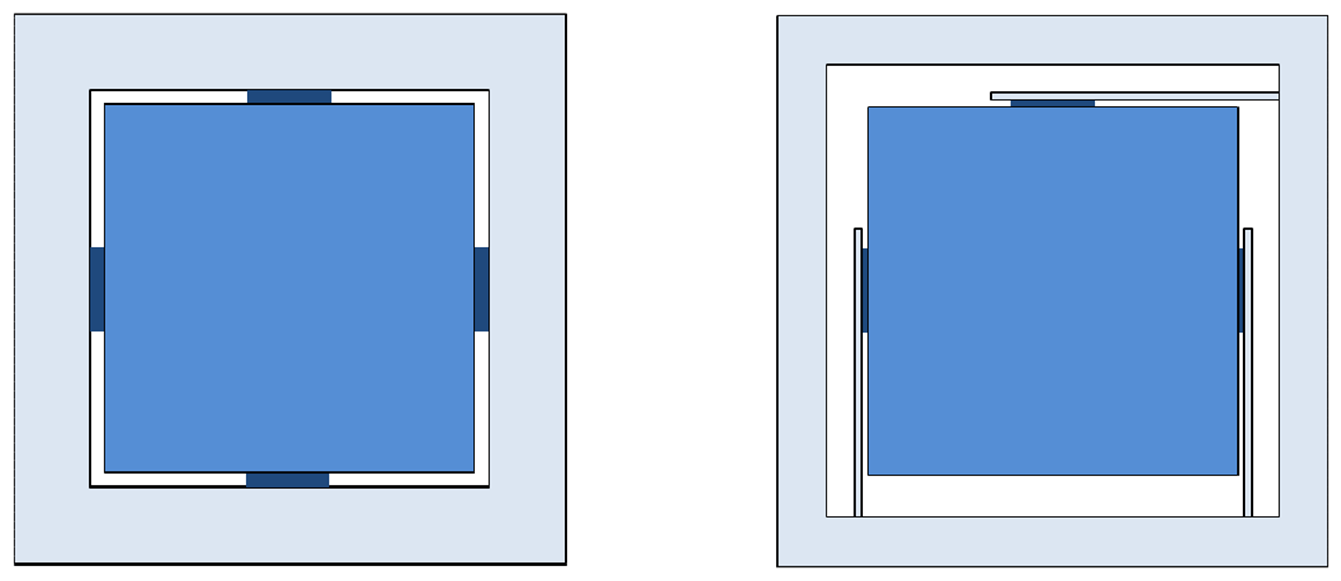
Figure 1 – Athermalization by CTE matching of the bond thickness (left) versus athermalization by applying elastic elements integrated in the mount (right).
Athermalization by tuning the bond thickness often results in thick bond lines. This is not beneficial for strength and stiffness of the bond. Furthermore it is usually difficult to match the CTE’s of all materials over a large temperature range, especially when considering the unavailability of reliable CTE data. The stability of this design depends on the symmetry of application of the adhesive and on the material stability of the adhesive. If the CTE match is not optimal then internal stresses arise in the bond and optical component, resulting in reduced stability and increased wave front errors.
A better approach to athermalize the mount is by introducing flexible elastic elements in the mount, such as a leafspring. When properly dimensioned, the tensile and lateral stiffness are much higher than the bending stiffness (as a rule of thumb a ratio of 1:1000 is achievable). The leaf spring can be manufactured with conventional inexpensive milling. Alternatively it can be manufactured using wire EDM.
A rigid optical component has 6 degrees of freedom (DOF). An isostatic design means that each degree of freedom is constrained only once. A leaf spring constrains three DOF with high stiffness, two translations and one rotation. Because a bond spot has high shear stiffness, but a low torsional stiffness, the combination of bond spot with a leaf spring only constrains the two translations with high stiffness. By arranging three leaf springs around the optical component as shown in Figure 2, the optical component is constrained once in each degree of freedom. Because of the isostatic design the mount cannot impose significant forces or bending moments on the optics and deform the optical component. The optical component is bonded on its neutral axis, which coincides with its center of gravity.
In practice true kinematic constrains do not exist and bending moments due to parasitic stiffnesses can have a second order influence. Wave front errors introduced by these parasitical forces must be checked by hand calculations or FEM analysis. The natural frequencies of the mount are high because each degree of freedom of the optical component is constrained with high stiffness. This is beneficial for the stability of the component under inertial loads (such as gravity). The arrangement of the leaf springs determines the location of the thermal center. If a temperature difference occurs between component and mount, the center of expansion is at TC. Because of the flexures, the thermal expansion difference between component and mount can be large without significant effects. Usually, the thermal center is located on the optical axis. The leaf springs decouple thermal expansion of the component in the lateral direction. Only residual local stresses in the glass arises around the bond spots. The effect of these remaining local stresses can be predicted by a FEM model of the bond spot in combination with an accurate material model of the adhesive.
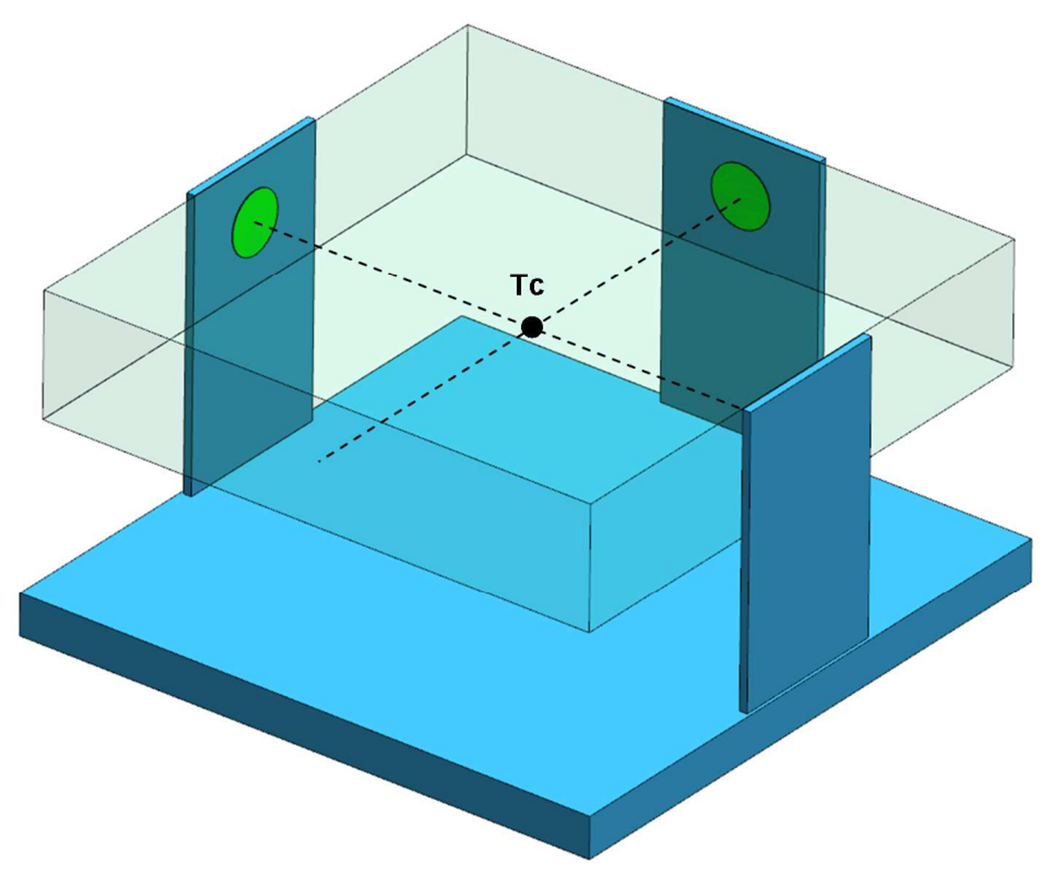
Figure 2 – Iso-static arrangement of a component that is bonded to three axial leafsprings, showing the location of the Thermal Center (TC).
The first application, shown in Figure 3, is the mount design for the TROPOMI instrument. Angular stability after launch loads and thermal loads are design driving in this application.
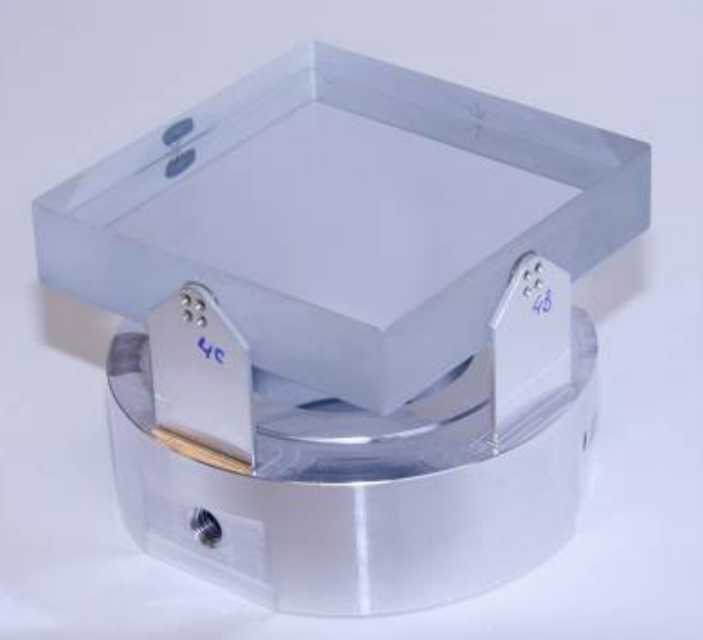
Figure 3 – Breadboard of the TROPOMI mount baseline showing three axial aluminium leafsprings bonded to a fused silica component. One of the bond spots is clearly visible (dark spot).
The second application, depicted in Figure 4, is a cryogenic mount for the GAIA Wave Front Sensor. Again stability and WFE are design driving but now not only in combination with vibration loads up to 30.2 g RMS but also in combination with an operational temperature range from 130 K to 200 K.
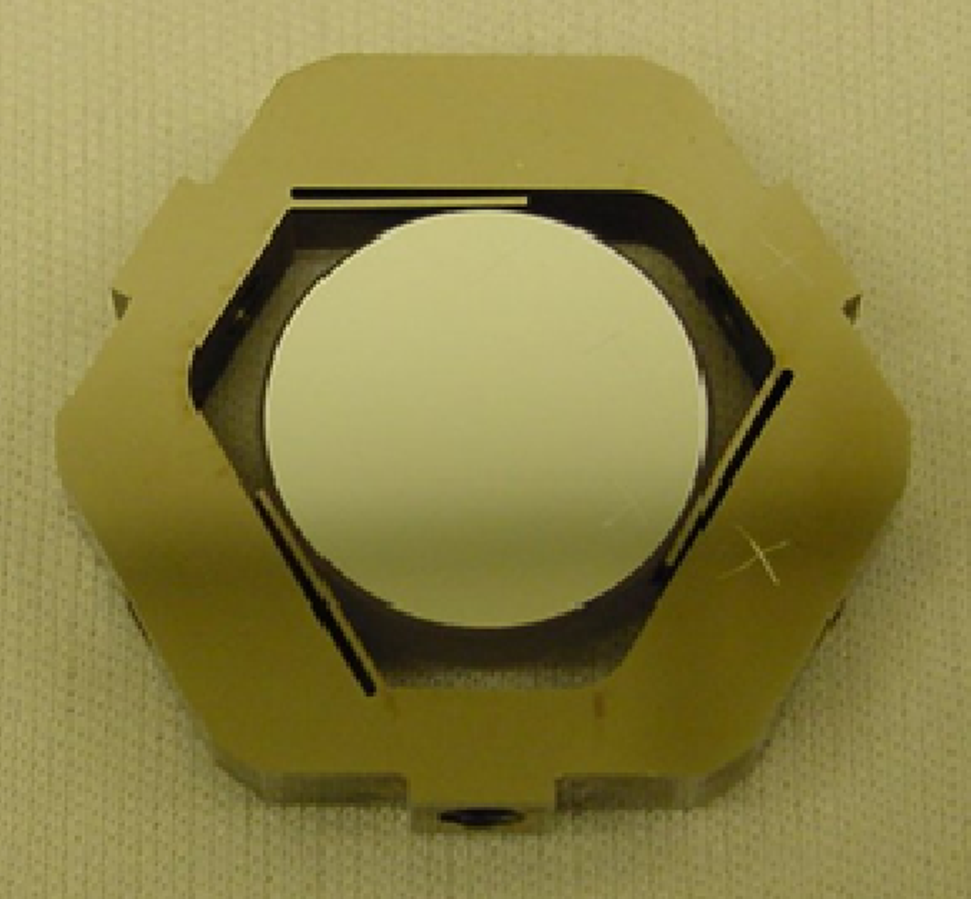
Figure 4 – Breadboard of a mirror bonded to three tangential leafsprings as used in the GAIA Wave Front Sensor mount design.
Development by TNO Optomechatronics
- Joep Pijnenburg, Martijn te Voert, Jan de Vreugd, Amir Vosteen, Willem van Werkhoven, Jeroen Mekking, Bjorn Nijland
References:
J. Pijnenburg, M.J.A. te Voert, J. de Vreugd, A. Vosteen, W. van Werkhoven, J. Mekking, B.A.H. Nijland, “Ultra stable iso-static bonded optical mount design for harsh environments”, SPIE ICSO, 2012