Chapter 2 - Design using flexures
Chapter 3 - Design for static stiffness
Effects of misalignments on the static and dynamic behavior of a multiple overconstrained compliant 4-bar mechanism
The use of overconstrained mechanisms is often avoided in precision mechanics. Exact constraint design ensures a mechanism has exactly the right amount of constraint (stiff) and free (compliant) directions.
However, this principle has some drawbacks such as limited load bearing capacity, limited support stiffness, asymmetry, and high stress concentrations at the attachments [11].
Overconstrained designs do not suffer from these drawbacks, but are sensitive to misalignments due to assembly, fabrication tolerances and (asymmetric) expansion due to heat sources. Misalignment causes internal stress which will cause unwanted static and dynamic system behavior, such as buckling and deteriorated support stiffness and faster fatigue. The consequences of misalignment on a single-overconstrained parallel leaf spring guidance and a single-overconstrained cross flexure have been investigated by Meijaard [1] and Nijenhuis [2]. A strong decrease in support stiffness was shown and it was concluded that practical mechanisms seem more tolerant to misalignment errors than the ideal bifurcation buckling load suggests, due to extra sources of compliance.
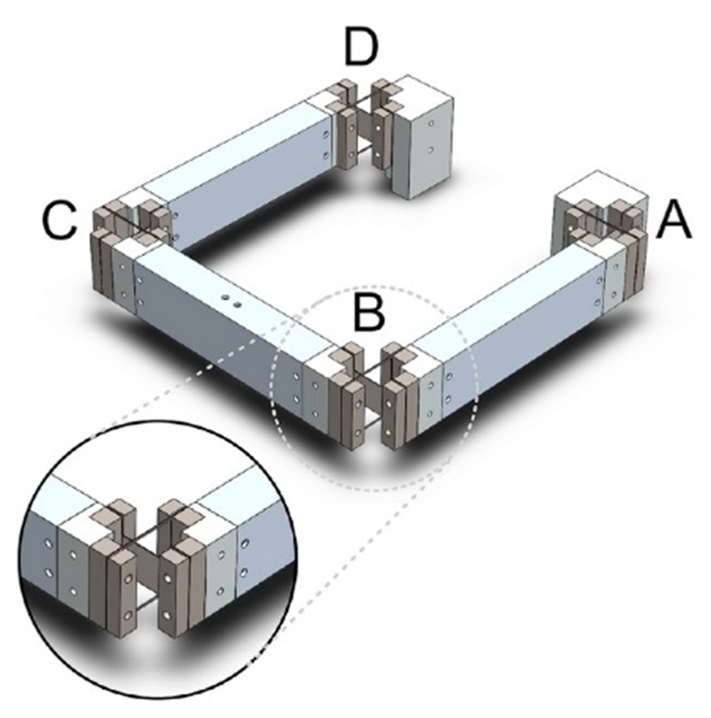
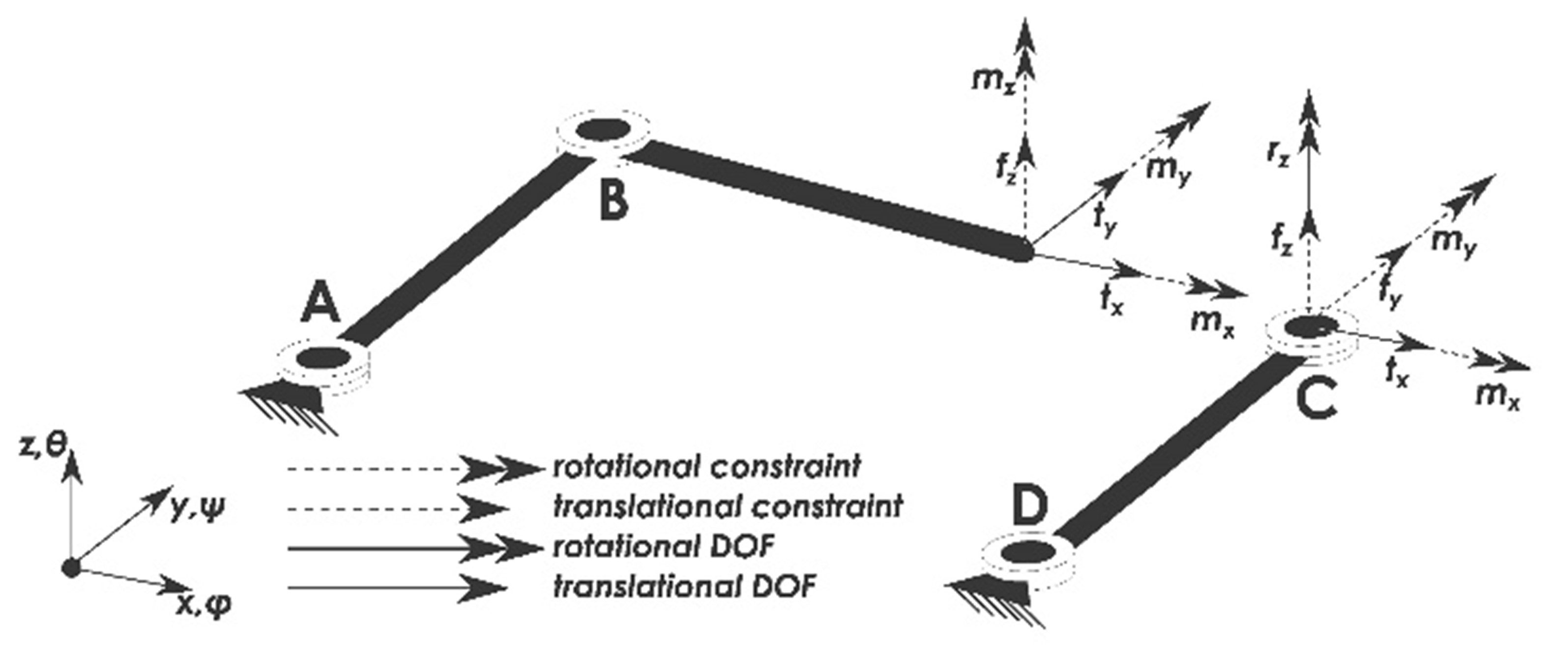
The effects of misalignment on a three-times overconstrained 4-bar mechanism are investigated. A method is introduced to identify the limits of these alignment tolerances. The method allows the calculation of the forces in the mechanism due to misalignment. The internal forces are compared to the buckling loads of the mechanism yielding the critical misalignments; the method is corroborated using a multibody simulations. Subsequently, both analyses are compared to measurements on an experimental setup. The proposed method and multibody simulation match with each other and the experiment. The modelled critical misalignments are within 20% of the critical misalignments of the experimental setup which is mainly attributed to hardware imperfections and the sensitivity of the imperfections on buckling behavior. The results can be used as a guideline to estimate the manufacturing and assembly tolerances of overconstrained flexure-based mechanisms.
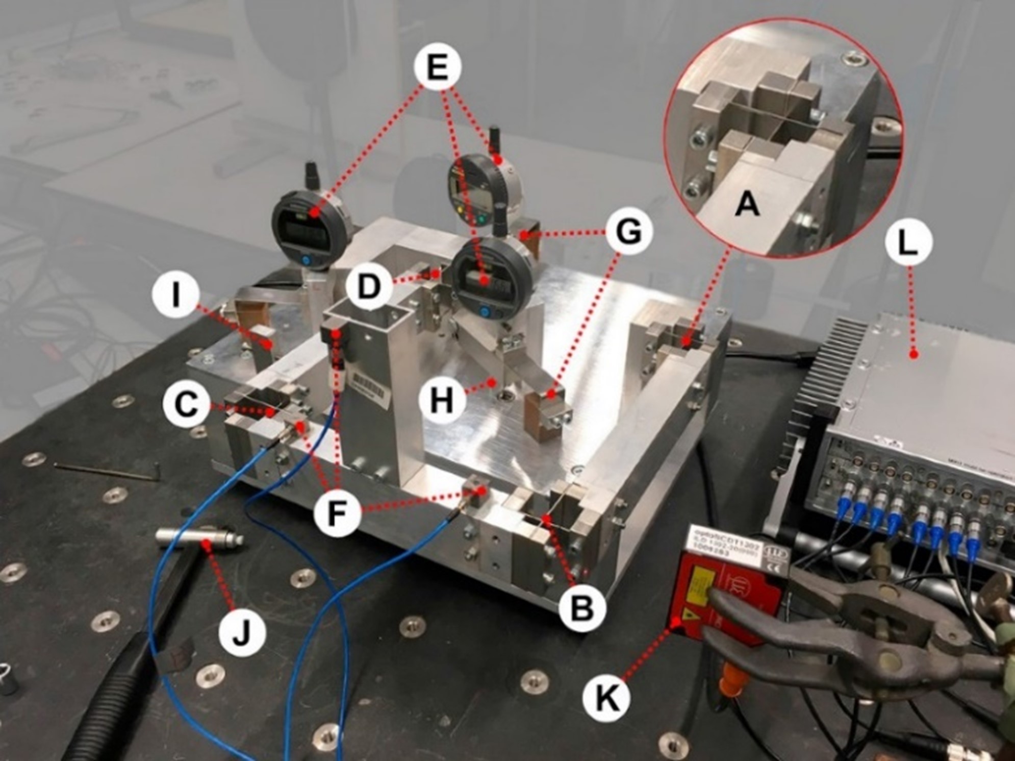
Figure 3. Overview of the experimental setup. There are four exactly constrained cross pivot flexures (A through D). At point D a manipulator connects the mechanism to the fixed world. The manipulator is constrained by three folded sheet flexures (G); The flexures constrain the movement in the in-plane directions (x, y and θ), but leave the overconstrained directions of the mechanism free. The goal is to be able to precisely align or misalign the three overconstrained directions by three screws (3H)in order to observe the change in behavior of the mechanism. The height of the arms is measured by three dial gauges (E). The vibrations of the end-effector are measured using three accelerometers (F).
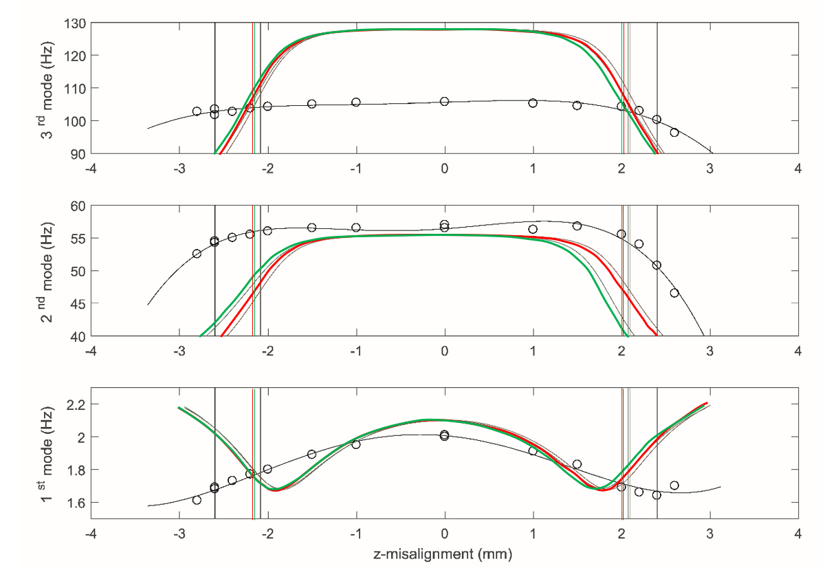
Figure 4. Change in the first three modes due to a misalignment in the z-direction, the critical misalignment (vertical lines). The experimental results, shown in black, are fitted on the measurement points (open circles). The simulation without and with gravity are shown in red and green respectively.
Principle
Based on relatively simple buckling equations the amount of misalignment where a flexure mechanism changes behavior can be predicted. These misalignments can be used to determine the manufacturing tolerances of a mechanism.
Conclusion
A guide is provided of how much misalignment can be tolerated in an overconstrained mechanism flexure-based mechanism. The effects of misalignment on a three-times overconstrained 4-bar mechanism are investigated. A method was developed to ascertain the amount of misalignment where buckling occurs; this buckling indicates the limits of optimal stiffness behaviour in the mechanism. The method is far less complicated and time-consuming than modelling the entire mechanism in question. The method was compared to full mechanism simulations. The introduced method has slightly higher values for the critical misalignments than the simulation: about 25% for the z-misalignment and 3% for the other two misalignments. This is likely caused by an improper assessment of the elastic boundary conditions. An experiment was done to validate the results of the method and simulation. A change in all three modal frequencies was observed due to all three misalignments. The values of the critical misalignments are about 20% higher than in the simulations, which can be explained by the visual observation of buckling and the imperfections in the hardware and assembly are likely to influence the behaviour. The approach outlined in this article can be adapted to fit other types of compliant mechanisms
Developed by University of Twente
W.W.P.J. van de Sande, R.G.K.M. Aarts, D.M. Brouwer
Referentie Bron
[1] J.P. Meijaard, D.M. Brouwer, J.B. Jonker (2009) Analytical and experimental investigation of a parallel leaf spring guidance, Multibody System Dynamics, 77(23), https://doi.org/10.1007/s11044-009-9172-4
[2] Nijenhuis, M., Meijaard, J.P., Brouwer , D.M. (2019) Misalignments in an overconstrained flexure mechanism: A cross-hinge stiffness investigation, Precision Engineering, Volume 62, 2020, pp.181-195, https://doi.org/10.1016/j.precisioneng.2019.11.011
[3] Werner W.P.J. van de Sande, Ronald G.K.M. Aarts, Dannis M. Brouwer, Effects of misalignments on the static and dynamic behaviour of a multiple overconstrained compliant 4-bar mechanism, Precision Engineering, Volume 60, 2019, Pages 143-151, ISSN 0141-6359, https://doi.org/10.1016/j.precisioneng.2019.06.010


