Chapter 2 - Design using flexures
Chapter 3 - Design for static stiffness
Flexures in a heavy duty H-drive gantry
Problem description
Aligning the two linear guides of an H-drive such that the carriages with traversing beam run smoothly over the range of motion without excessive internal forces is difficult, in particular if thermal changes are involved. Therefore, and (almost) exact constrained solution is proposed by Koster [1] and Soemers [2]. Basically a leafspring in the XZ-plane (see Figure 1 for coordinate system) at each end of the traversing beam, between the beam and the carriage at each end, and a wire-flexure in the Y-direction between the beam and one of the carriages fully constrains the beam. Only a single overconstraint in the rY direction exists, which is allowable because the variation in rY between the two carriages is limited. The combination of the overcostraint and misalignment then do not lead to significant stress.
However, for certain manipulation operations with large interaction forces while precision is required too, the (almost) exact constraint solution proposed by Koster [1] and Soemers [2] is stiffness wise insufficient in the Z and rY direction.
To obtain the required stiffness two pairs of parallel rails with in total 12 carriages are used, as shown in Figure 1. Each carriage effectively constrains four directions, with X free and rX relatively compliant. If this system would be rigidly connected including the two actuators, it would be many times overconstrained.
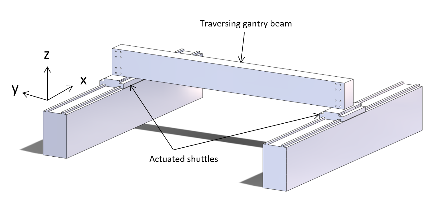
Figure 1: Granite traversing gantry beam
Concept
The concept will be explained examining one end of the traversing beam first.
Three carriages move over one guidance, which is overconstrained, but with the high quality flatness of the granite support material of the guidance, and the low tolerances of the carriages themselves, which are connected to a high quality flatness granite shuttle, this overconstrained architecture is allowable with the residual minor variations being averaged elastically, equivalently to a roller bearing. Note that granite can be made very flat, in the order of microns per meter. The granite guidance support and granite shuttle are shown in Figure 2.
A second straight guidance, close to the first, is placed atop the granite support material, so the two guidances are within very small tolerances in a horizontal plane, allowing for overconstraints in Z, rX and rY direction. Of these overconstraints, the rX direction of the individual guidances is relatively compliant anyhow. The Y and rZ direction of the second guidance are self-aligned with respect to the first guidance by using the shuttle to move over the entire range of the guidance, and ensuring the carriages move freely. The second guidance is then bolted to the granite. Because the guidances are close to each other the overconstraints in the Y and rZ direction will not lead excessive stress, even with some thermal expansion. The connection between the six carriages in the shuttle can therefore be made rigid.
The stiffness is particularly important for the Z and rY direction. A leaf spring solution equivalent to the solution proposed by Koster [1] and Soemers [2] has these forces in-plane. However, the forces then need to be distributed by the shuttle over the carriages which will cause the shuttle to deform. Also, for sufficient rY and Z- stiffness the leafspring would be need to be extremely thick, becoming too stiff in the Y-direction. Therefore, each of the leafsprings is positioned with its plane collinear to one of the two guidances. Because of the distance between the two leafsprings formally the two leafsprings act as a parallel leafspring linear guide. The second leafspring constrains the three rotations extra compared to the single leafspring solution by Koster [1] and Soemers [2]. The rZ and rX overconstraints are not very stiff, but their respective misalignment needs to be kept within bounds. The rZ-misalignment is kept within bounds by the controller of the two actuators. The rX-misalignment is kept to a minimum by allowing low stress alignment of the traversing beam within a steel bracket with through bolts, see Figure 3. The rY-misalignment is kept to a minimum when assembling the leafsprings with the shuttle and bracket. Note that the rY-direction was on purpose already overconstrained in the original solution by Koster [1] and Soemers [2], and posed no issue there.
The other end of the traversing beam has an equivalent architecture but then mirrored. To include enough Y-stiffness, an asymmetric ‘coupling-rod’ is added in the Y-direction on one side, shown in Figure 4.

Figure 2: Photo showing the thickness of the leafsprings
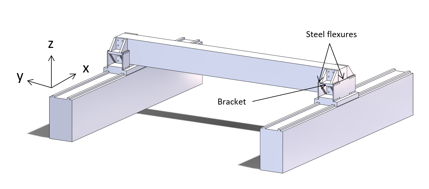
Figure 3: Granite traversing gantry beam, supported by flexures
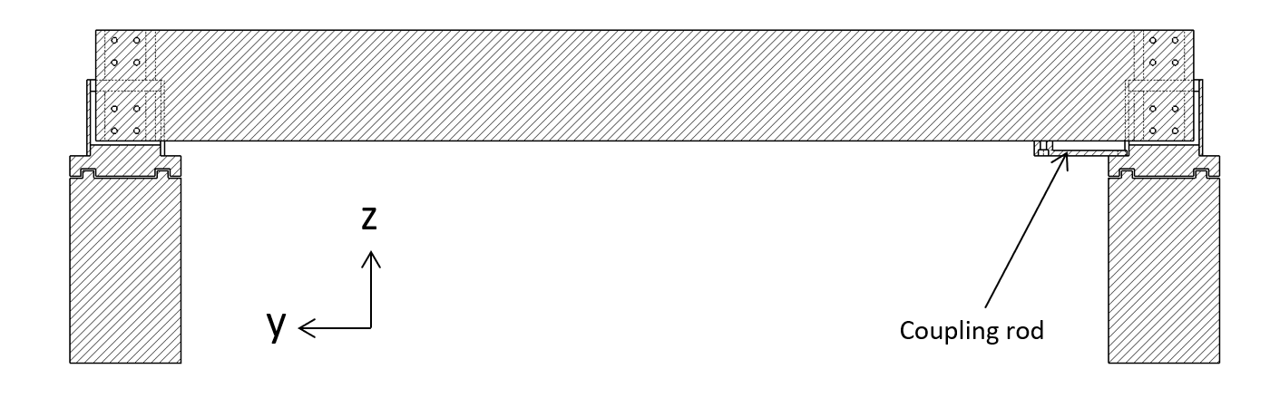
Figure 4: Granite traversing gantry beam, cross sectional view
References
[1] M.P. Koster, Constructieprincipes, Universiteit Twente, 1998.
[2] H.M.J.R Soemers, Design Principles for Precision Mechanisms, T-Pointprint, Enschede, 2010.