Passive damping in semiconductor wafer stages
Unlike automotive and aeronautic systems, high tech systems have been designed as mass-spring system with hardly any damping, primarily for reproducibility reasons. Recently, the implementation of passive damping was added to realize suppression of amplifications at resonances and thereby, sufficient exponential decay of undesired vibrations in uncontrolled degrees of freedom. Passive damping, which was abandoned for a long time in view of the risk of position uncertainty by hysteresis, became a new design paradigm in the 2010s.
Description
Since mode shapes of traditionally designed motion stages are only lightly damped, further bandwidth increase is hampered. In the design of a 450 mm wafer chuck, it was observed that at about 3 kHz, a significant fraction (80-90%) of the chuck mass internally decouples due to two global horizontal bending modes resulting in the actuator interface, causing broad anti-resonance/resonance behavior. The dynamic flexibility in the actuator interface was exploited to attenuate high-frequency amplifications at resonance through local implementation of broadband viscoelastic damping. A viscoelastic material was selected with a sufficiently large loss angle in the frequency range of interest, and geometrically tuned such that at low frequencies, the elastic stiffness of the metal flexure support dominates to avoid long term creep effects, and from 500 Hz onward, the viscoelastic stiffness takes over. From 10 kHz onward, the elastic stiffness of the ceramic chuck again is limiting, resulting in a mechanical lead-lag filter, comparable to a tame PD action in controls (see Figure 2). The behavior was experimentally verified in a representative section of a wafer chuck (see Figure 3). A significant attenuation of about 30 dB was observed at dominant resonant modes in the 1-4 kHz range (see Figure 4).
 Figure 1. Performance of traditionally designed mass-spring systems is limited by high-frequency modes, damping opens up the solution space. | 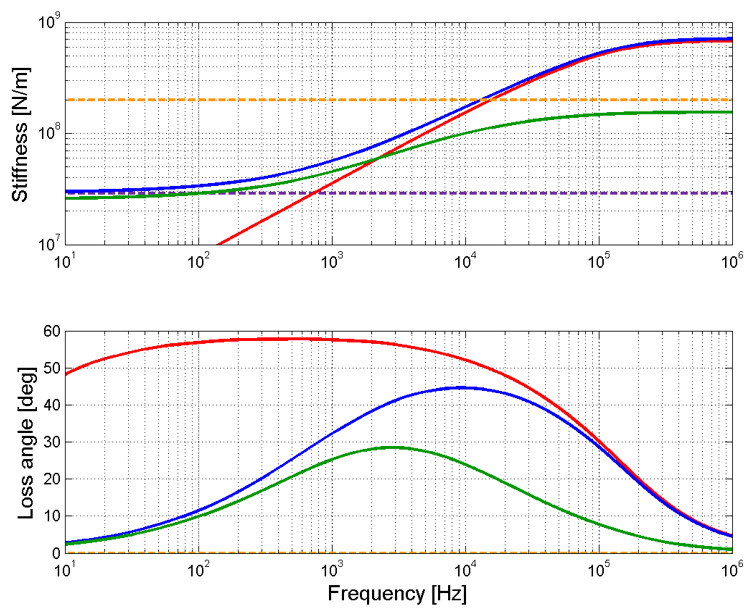 Figure 2. Dynamic stiffness and loss angle of implemented in the actuator elastic support. The elastomer introduces broadband damping in the resonant frequency range, similar to a lead-lag filter in control. |
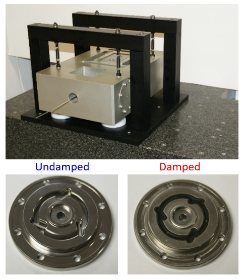 Figure 3. Simplified 1D test setup that mimics the actuator-chuck-sensor interaction (top), and undamped and damped actuator support (bottom). | 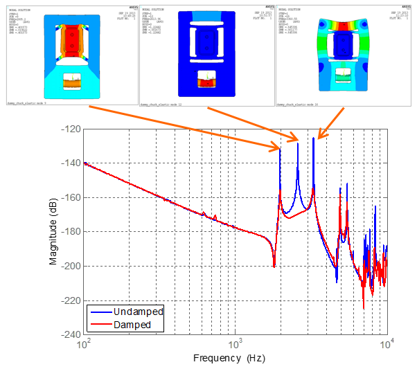 Figure 4. Magnitude plot of the transfer function from actuator force to sensor displacement for the undamped (blue) and damped (red) actuator support. About 30 dB attenuation is observed in the frequency range 1-4 kHz. |
Application:
Semiconductor wafer stage
Realized:
Broadband damping in actuator interface
Principle:
Design for damping w/o affecting quasi-static reproducibility.
References
[1] Meulen, S., van der, Aangenent, W., Enabling overlay and focus improvement via passive damping in ASML motion stages, Proc. of the 3rd DSPE Conference on precision mechatronics, October 5, 2016.
[2] Vermeulen, J.P.M.B., Passive damping in high-tech systems, Lecture notes, 4CM50 Applications of design principles, May, 2021.