Chapter 2 - Design using flexures
Chapter 3 - Design for static stiffness
Optimal release locations in assembled overconstrained mechanisms for static determinacy
To ensure a deterministic behavior the assembled mechanisms are often made exactly constrained. In overconstrained mechanisms inherent alignment errors cause self-stress. The level of stress can be reduced by inserting flexure releases making the mechanism exactly constrained. The location and orientation of releases can be optimized for a combination of minimum self-stress and maximum stiffness. The kinematics of a four-bar mechanism with inherently three overconstraints is analyzed using methods (1) opening the four-bar loop and examining the constraints from two sides, and (2) Grüblers criterion. Three releases are required to obtain an exact constraint mechanism. Nine locations in the four-bar mechanism are investigated. The optimal release locations with respect to maximum support stiffness and low self-stress due to misalignment in the overconstrained directions are presented.
In the simple example of a four-bar mechanism the overconstraints can be visualized by opening the four-bar loop and examining the constraints as shown in Figure 1. The in-plane vectors $x_A$, $y_A$, $\theta_A$, $x_B$, $y_B$ and $\theta_B$ show three DOFs. The translational DOFs $x_A$, $y_A$ and $x_B$ are not pure translations, but respectively a parallel motion, a rotation around h2, and rotation around h4. An additional DOF is introduced by hinge h3 connecting the two arms. Only one arm constrains the y-direction and the q-direction is constrained only once. In the x-direction both arms are free. Therefore, the linkage has one in-plane DOF. The out-of-plane vectors shows six constraints $z_A$, $z_B$, $\varphi_A$, $\varphi_B$, $\psi_A$ and $\psi_B$ where three are required to exactly constrain the out of plane direction. The mechanism is therefore three times overconstrained and has one free motion. The free motion is intended, because it will be controlled by some kind of actuator, and is therefore not of interest here. Three releases should be implemented in order to obtain an exact constraint mechanism.
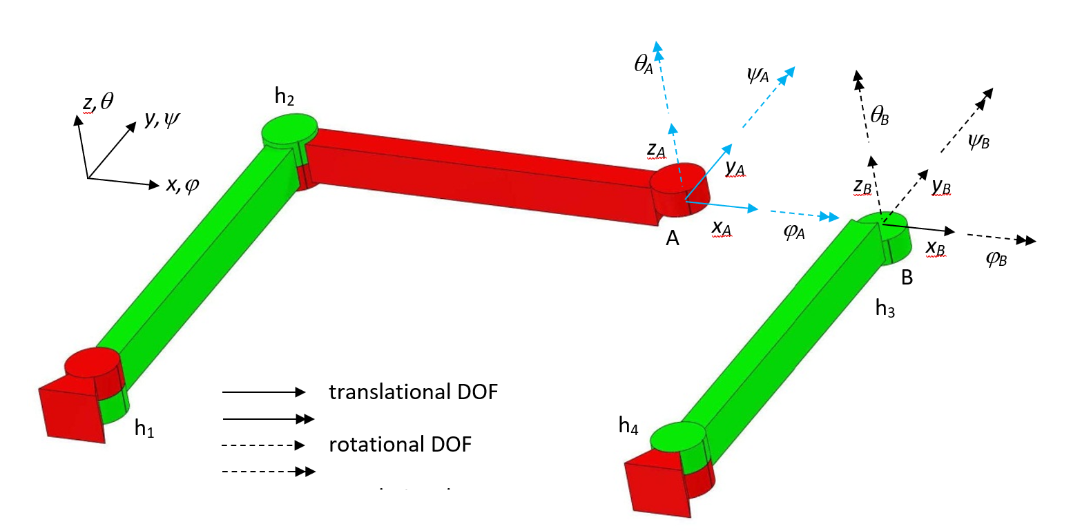
Figure 1. The loop of a four-bar linkage opened. The DOFs (solid vectors) and constraints (dashed vectors) are shown for the left coupler A (in blue), and the right coupler B (in black).
The number of DOFs and overconstraints can also be analyzed by using Grübler’s criterion. In a two-dimensional analysis the three DOFs of each of the four rigid bars sum up to twelve DOFs. The four hinges each constrain two DOFs so there are in total eight constraints and only four DOFs remain in the system. The three rigid body modes of the four-bar mechanism are not considered and are also subtracted from the system’s DOFs. Then in total there is one DOF more than there are constraints as is summarized in Table 1. The DOF allows exactly one motion, so there is no overconstraint. If the motion is the intended motion of the manipulator, and the motion is actuated, the 2–D mechanism is exactly constrained. The mechanism can also be analyzed including the third dimension by Grübler’s criterion. The four bars now give rise to 24 DOFs, the four hinges impose 20 constraints, and 6 rigid-body modes are not considered. As shown in Table 1 this results in two more constraints than DOFs. As the four-bar linkage has one intended DOF, shown by the two-dimensional Grübler analysis, there have to be three overconstraints. The overconstraints do not appear in the two-dimensional analysis, but do show up in the three-dimensional analysis. Apparently, the overconstraints are related to the out-of-plane directions. As in the previous section we conclude that three releases and one actuator are required to obtain an exact constraint mechanism.
| 2D | 3D | ||
| # Rigid bars (n=4) | 12 | 24 | DOFs |
| # Constraints of hinges (s=4) | -8 | -20 | DOFs |
| Rigid body modes of mechanism | -3 | -6 | DOFs |
| DOFs – constraints – rigid body modes (M) | 1 | -2 | DOFs |
| Real mobility | 1 | 1 | DOFs |
| Overconstraints | 0 | 3 |

Figure 2. Nine possible locations hb11, hb12, hb13, hb21, hb22, hb23, hb31, hb32 and hb33 for implementing releases in a four-bar mechanism have been researched.
The overconstraints of the four-bar mechanism can be removed by implementing three releases. Rotational releases are examined because releasing translations, either sliding or flexure based, is more difficult than releasing rotations by a bearing or a flexure. The location to consider rotational bending releases is at the ends of the beams, because at these locations the bending moments are the largest. Torsional releases are implemented in the middle of the beams. In total 9 release locations are investigated, shown in Figure 2. An example is given in Figure 3 where three releases are implemented using hinges. The exact constraint design is tolerant of misalignments. For example, misalignment in any of the six DOFs is possible at the connections with the base. The three in-plane DOFs are accounted for by the standard hinges of the four-bar mechanism. The three misalignments in the out-of-plane DOFs $z$, $\varphi$ and $\psi$ induce rotations of the three extra hinges. Figure 3 shows these misalignments at one of the base connections.
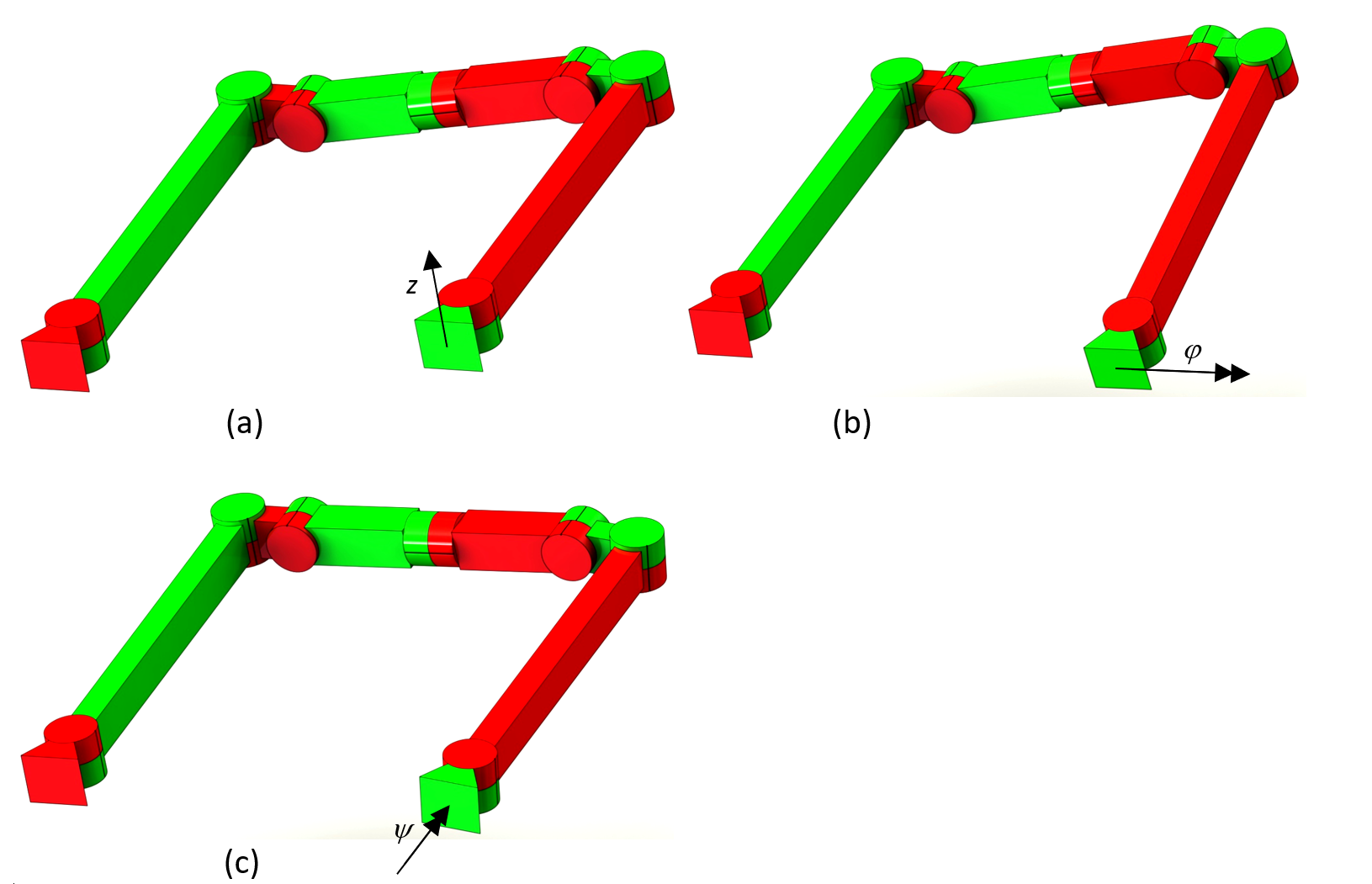
Figure 3. An example of three possible release locations to prevent misalignment in any of the three overconstrained directions to result in self-stress a) Misalignment of one of the base connections in $z$-direction, b) in $\varphi$ -direction, c) in $\psi$ -direction.
The location and direction of the releases influences the self-stress distribution and the stiffness of the mechanism. Therefore the location and direction of releases can be optimized for minimum self-stress and maximum support stiffness over a certain range of motion of a mechanism. The four-bar mechanism consists of four in-plane hinges without stiffness, h1 – h4. There are nine out-of-plane hinges, hb11, hb12, hb13, hb21, hb22, hb23, hb31, hb32 and hb33, shown in Figure 2. Three of these are implemented with a small stiffness and six are implemented with a large stiffness. There are 84 such configurations, of which 44 exactly constrained. The support stiffnesses in $z$-, $\varphi$- and $\psi$ -direction of beam b2 are calculated at the position of the hinge hb23 [1]. These stiffness are scaled. Misalignments in Δ$z$, Δ$\varphi$ and Δ$\psi$ are introduced and the rotations of the hinges (αbij) in the hinges (hbij) are calculated. The maximum moment in the hinges as a result of the misalignment of the base connections in $z$-, $\varphi$ – and $\psi$ -direction is calculated and scaled. Each of the 84 configurations fits in one of the three categories with respect to the stiffness and moment:
Category 1) Large stiffness, and small moments
Category 2) Large stiffness, and large moments
Category 3) Small stiffness, and large moments.
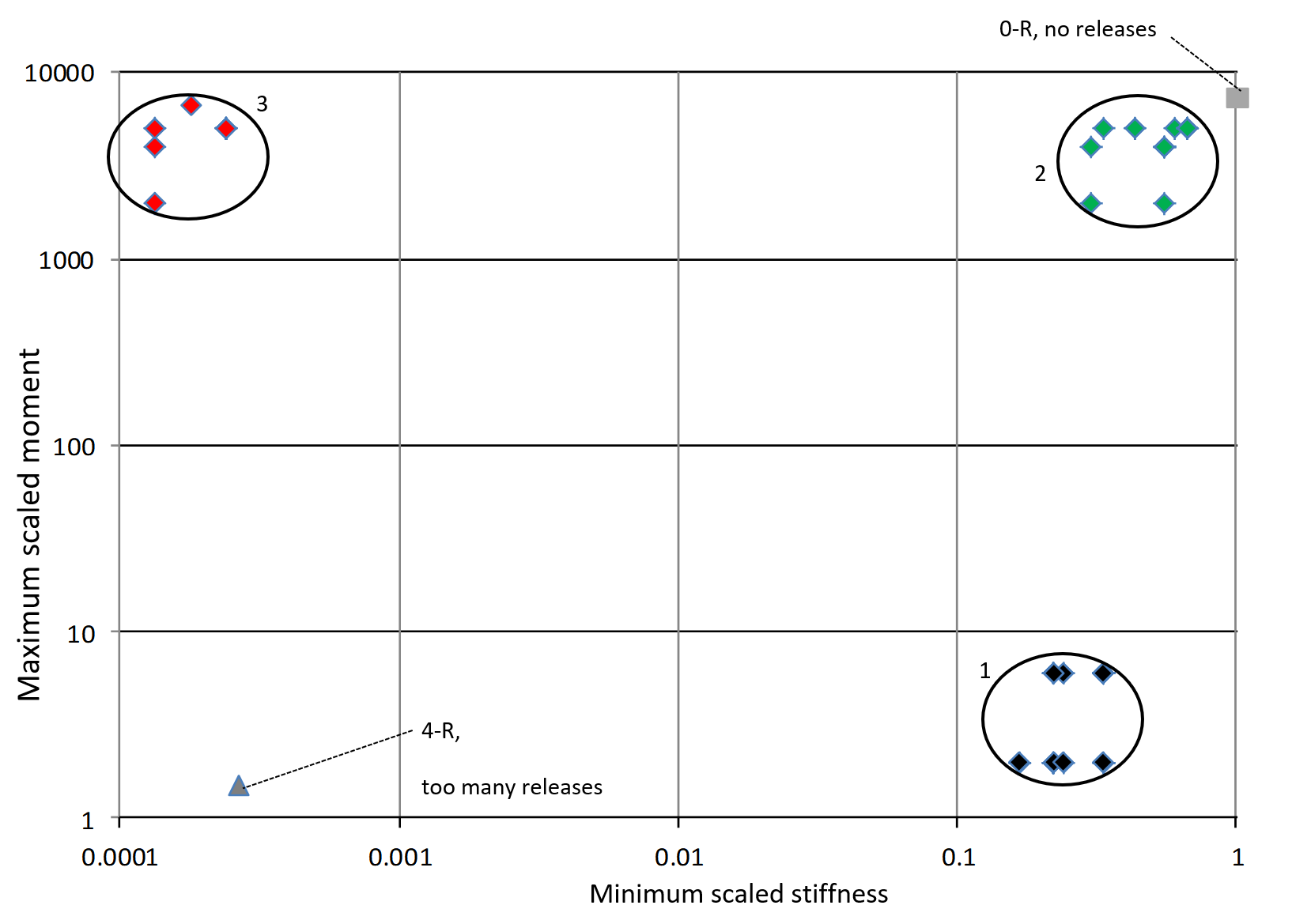
In Figure 4 the minimum stiffness value for each configuration k is plotted against the maximum moment of the three misalignments. The three categories are shown.
Category 1 are the exact constrained configurations. The configurations with releases near the end effector perform the best in terms of stiffness. The case study showed that an overconstrained four-bar mechanism without releases shows 2.6 to 3.4 times more stiffness than the exactly constrained configurations with the largest stiffness at the cost of large self-stress when the mechanism is misaligned. Therefore, if stiffness is of the utmost importance, overconstrained systems can be considered at the cost of tight tolerances to minimize misalignment and self-stress.
Principle
In overconstrained mechanisms inherent alignment errors cause self-stress. The level of stress can be reduced by inserting flexure releases making the mechanism exactly constrained. To make a four bar mechanism with five constraints per hinge exact constraint, three releases are required. The three release are best located near the end effector to obtain the highest support stiffness.
Developed by University of Twente
D.M. Brouwer, S.E. Boer, J.P. Meijaard, R.G.K.M. Aarts
Reference
[1] D.M. Brouwer, S.E. Boer, J.P. Meijaard, R.G.K.M. Aarts, Optimization of release locations for small self-stress large stiffness flexure mechanisms, Mechanism and Machine Theory, Volume 64, pp. 230-250 (2013). DOI: 10.1016/j.mechmachtheory.2013.01.007
[2] D.M. Brouwer, K.G.P. Folkersma, S.E. Boer, and R.G.K.M. Aarts, Exact Constraint Design of a Two-Degree of Freedom Flexure-Based Mechanism, Journal of Mechanisms and Robotics (ISSN 1942-4302) 5(4), 041011, pp. 10 (2013). DOI: 10.1115/1.4025175