Chapter 6 - Design for low friction and hysteresis
Flexure damping with minimal virtual play
Elastic elements or flexures are frequently used in high precision mechanisms for relatively small displacements and rotations without (virtual) play, as well as in kinematic mounts to avoid over-determination in part connections and to create a thermo-mechanically stable fixation for high precision optical components. Flexures enable high accuracy and very deterministic behavior at relatively low cost. To meet extreme demands on e.g. thermal stability and reproducibility, flexures are preferably made monolithically, e.g. via wire EDM, however, at the cost of a significant amplification at resonance, i.e. lack of sufficient damping. Monolithic components are disadvantageous for dynamic loading, as vibrations (especially at resonance frequencies) will continue to exist or even be enlarged instead of damped out. Without an external damping treatment, only material damping of metal flexures is present, which is negligible.
Description
Generally, machine structural components are made relatively stiff and as a result, often the first natural frequency arises at a part interface. Especially for kinematic mounts for optical components based on flexures, the trade-off between high bandwidth of the positioning system and thermal stability of the sensor reference (mirror) requires quite some iterations in the design. The same holds for the design of the kinematic mirror mount shown in Figure 1 that is used in a nm-level positioning system with distance measuring interferometers (DMIs). As a result of high amplification at resonance in monolithic flexures (102-103), eigenfrequencies in the 600-800 Hz range are required (both for internal and suspension modes) for a bandwidth of the positioning system in the order of 100 Hz (see Figure 2).
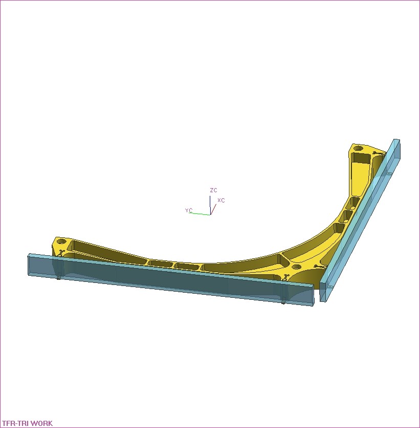 | 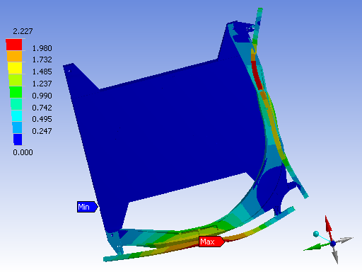 |
| Figure 1. Kinematic mount for Pyrex glass mirrors (CTE = 3.3×10⁻⁶ [K-1]) to aluminum mirror frame (CTE = 24×10-6 [K-1]). | Figure 2. Undamped vibration mode of mirrors at mount at 844 Hz. |
In the original manner of incorporating flexures in structural components, the elastic parts itself, such as leaf springs and elastic rods were fixed by means of clamped joints. And although damping, obtained from dry or lubricated interfaces may provide an important mechanism of energy dissipation, the amount of damping is still an order of magnitude less than what is desired for optimal performance. Moreover, as far as the accuracy and reproducibility of machines and instruments is concerned, it would be best if joints would behave as rigid interfaces instead of slip planes, and therefore, enable a deterministic behavior by the absence of virtual play.
For significant energy dissipation without virtual play, the dissipating forces should only contain velocity dependency (return to zero position) and as a result, viscous damping treatments are ideal for PE applications. However, sealing the viscous fluids is difficult and introduces friction and related virtual play. As an alternative, [5] proposes low-wave-speed media, such as foam to provide damping for flexural vibrations. This ‘Lodengraf’ damping, found for low-density granular fills, behaves similar to compressible fluids with a low speed of sound.
Instead of viscous (like) damping treatments, viscoelastic damping treatments are often used in engineering practice, enabling a very compact damping mechanism for flexures. The incorporation in the design, however, requires special attention. Since over-constraints to the system will disturb the accuracy and deterministic behavior of the intended kinematic design, it would be advantageous if damping were included within the flexure elements itself [6].
Relatively thin viscoelastic blobs or layers applied to surround flexures as found in literature are not very effective in energy dissipation, as these blobs or so-called ‘free’ layers are loaded by tension and compression instead of shear stress, for which the amount of strain (dictated by the metal flexure) is significantly smaller, and so is the amount of hysteresis (energy dissipation).
Compared to thin free layer damping (FLD), constrained layer damping (CLD) is far more effective [4]. CLD has been used for many years in many different applications, among others consumer products, aviation, e.g. in helicopter blades, bridges and machine tools. Damping is achieved by imposing shear strain on viscoelastic layers that are laminated between the structural member and constraining metal layers. Strain results from relative motion between the metal parts. In case of bending or torsion, motion is greatest far from the neutral axis, especially when interface surfaces move in opposite directions. Different analytical models are developed to determine the optimal layer thickness in CLD, e.g. the RKU method and the Model Strain Energy method [5], [6]. The CLD treatment is able to dissipate energy over a large frequency range and is rather insensitive to the vibration amplitude. Since viscoelastic shear forces tend to stretch the structural constraining layer, very thin constraining layers are not effective.
The idea here is to locate the constrained viscoelastic damping layers at the flexure-based interfaces, at that particular spot where the deformation for suspension modes is concentrated, i.e. at the dominant compliant part responsible for the resonant behavior. Consequently, a significant amount of damping may be introduced, and moreover, additional over-constraints in the mount are avoided, which is highly advantageous for preserving the deterministic behavior of the original kinematic design. This way, the uncertainty level associated with thermal deformation of the mirrors is minimized, enabling error compensation by means of mirror maps.
Since damping in viscoelastic materials is obtained from hysteresis in the force-displacement relationship, the implementation of damping in PE applications may imply a compromise between the amount of damping and the associated virtual play $s_v$. From the elliptical expression of the hysteresis loop of a viscoelastic material, the associated (quasi-static) virtual play can be calculated. Here, both the viscoelastic stiffness [N/m] and the material loss coefficient $\eta_v(\omega)$ [-] are frequency dependent.
Due to the parallel connection of the viscoelastic material and structural metals in CLD materials, however, the associated virtual play can be designed to an acceptable level for a specific application. This is possible due to the frequency dependency of the stiffness of the viscoelastic material. Typically, the quasi-static shear modulus is one to two orders of magnitude smaller than the dynamic modulus in the 100-1000 Hz region (see temperature-frequency Nomogram). As a result, $c_v(0)<<c$ (where $c$is the elastic stiffness of the structural metal), and so, the (quasistatic) virtual play $ \lim_{\omega\to\infty} s_v=2X \eta_v(0) \frac{c_v(0)}{c} $ can be limited to the nm range.
Depending on the application and the dominant suspension mode (tension, bending, torsion), the design of CLD in flexures is focused on a certain DoF. Below, damping of a leaf spring in axial direction is considered. Two alternatives are shown, one for which damping is realized over the mid-section of the leaf spring (Figure 3), the other for which damping is concentrated in the hinged portions at each end (Figure 4).
 | 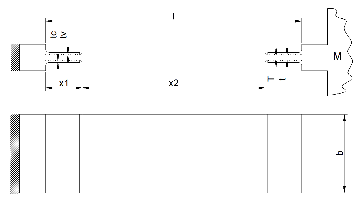 |
| Figure 3. Constrained layer damping over mid-section of leaf spring. | Figure 4. Constrained layer damping concentrated in hinged portions at each end. |
To calculate the amount of damping in axial direction, first the related complex stiffness $c_{ax}^*(x)$ [N/m] is determined, in this particular case for the leaf spring design of Figure 3. The axial stiffness is determined by a number of parallel and series connections of viscoelastic and elastic (metal) springs. By adding the two undamped metal end-portions and entering the complex shear modulus of the viscoelastic layers $G^*=G(\omega)(1+j \eta_v(\omega))$ [N/m2], the complex axial stiffness $c_{ax}^*=c_{ax}(1+j \eta_{ax})$ [N/m] arises. Next, from the ratio of the imaginary and real part, the loss factor $\eta_{ax}$ at the resonance frequency is calculated. Finally, the relative damping follows from $\zeta_{ax}=\frac{1}{2}\eta_{ax}$ [-].
For the design of Figure 3, the relative damping in the leaf spring with CLD is 8.5% (loss factor $\eta_{ax}$), which is a factor of 102-103 more than for the undamped leaf spring. As a result, the amplification at resonance is reduced with a factor of 33 (30 dB). The (quasi-static) virtual is in the nm range for (quasi-static) forces up to 100 N. This is negligibly small compared to (sub)micron thermal drift over time.
| Application: Precision engineering applications. | Realized: Attenuation of vibration amplitudes by 2-3 orders compared to damping in monolithic flexures. | Principle: Viscoelastic CLD in flexure with minimal virtual play. |
References
[1] Vermeulen, H., Hendriks, B., Rosielle, N., Eijk, J. van, Effective damping in mirror mounts, Proc. of the ASPE 2005 Annual meeting, Norfolk, VA, pp. 242-245, October 9-12, 2005.
[2] Hendriks, A.C., Passieve demping in mechanische systemen, Master’s Thesis (in Dutch), Eindhoven University of Technology, The Netherlands, 2004.
[3] Vermeulen, J.P.M.B., Hendriks, A.C., 2004, Elastic interface device, Philips Patent Application PHNL040135.
[4] Marsh, E.R., Slocum, A.H., 1996, An integrated approach to structural damping, Precision Engineering, Vol. 18, No. 2/3.
[5] Johnson, C.D., 1995, Design of passive damping systems, ASME, 50th Anniversary of the Design Engineering Division, Vol. 117 (B).
[9]6Hekma Wierda, J.E. 1997, Nat. Lab Technical note NL-TN 001/97, Vibration control by means of constraining layers.
Development
Bart Hendriks, Hans Vermeulen, Eindhoven University of Technology (2004)