Structural optimization of stiffness per unit of mass
A design, in which the material involved is used poorly in terms of deriving stiffness from solids, may be characterized by unfavorable loading. Often, the lines of action of forces do not coincide with the neutral axes of cross-sections, and accordingly, bending moments are induced, which negatively influence structural stiffness [1].
For relatively large protruding lengths or span lengths in structures, such as in hoisting cranes, a statically determined truss structure is conveniently offering high stiffness at system nodes. Optimizing truss structures involves preventing sharp angels between trusses and joints. For improving buckling resistance, tube-like trusses can be applied, thereby improving natural frequency as well. Node connections, however, become more complex.
In constructions that are loaded relatively near to their support (having a relatively broad base), closed boxes of plate material can offer very stiff and lightweight alternatives. Here, the share of (in-plane) shear stiffness of plates offers a significant contribution, which is not present in trusses [2]. Separate closed boxes may be interconnected and structures originating in such manner should only be loaded at the ribs and corners, leading to only in-plane loading of plates. In addition, large unsupported plate areas should be avoided to prevent low frequency resonances due to lack of out-of-plane bending stiffness of thin plates.
Description
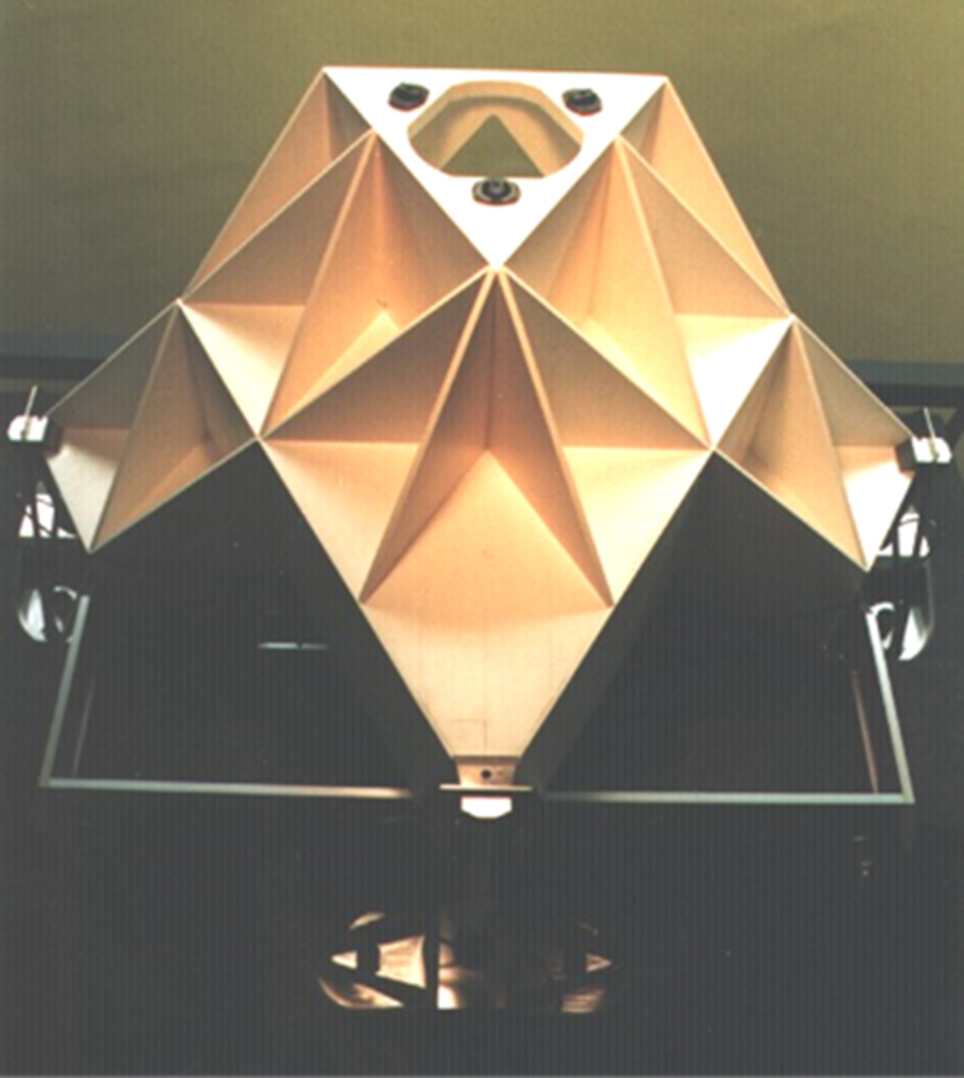
For the above considerations, a plate frame structure was applied in the design of a single point diamond turning (SPDT) machine [3], [4], [5]. The cross slide structure of the SPDT machine, is depicted in Figure 1. It is built up from short equilateral triangular tubes mounted face-to-face, and sandwiched between floor panels (compare the building of an apartment house). Triangular tubes were applied both for stiffness and manufacturing reasons. In fact, the triangular cross-section is statically determined and therefore, triangular tubes would not (necessarily) need end-plates for increasing stiffness. This is only applicable, however, for tubes with a considerable length compared to the (largest) width of the plates, as in this case, the shear stress distribution is no longer parabolic in axial direction but simply constant [2], [6]. In shorter tube-like structures, however, where the length is in the order of width of plates, the effect of bending stress dominates and end-plates help to keep the structure undistorted under forces within the plane of cross-section, and consequently improve stiffness. For this reason, end plates are applied as ‘floor panels’ to make up closed triangular boxes, a shown in Figure 1.
Uniform stress distribution
Designing in terms of transmission ratio i with its impact on stiffness (proportional to i2) as typical for mechanisms (see [7]), becomes less trivial when designing plate frame type structures. The same holds for the question whether parts (plates) should be considered or modelled in series or in parallel. For linear elastic structures, however, the overall stiffness c is related to the elastic energy content, which comprises the sum of the elastic energy content Ue,j of the individual parts j. For parts loaded in series, e.g. by tension or compression, the most compliant one absorbs the major part of the elastic energy. In order to increase the overall stiffness cs this most compliant part should be stiffened further at the expense of other parts. For parts loaded in parallel, the stiffest part (because of its shape, its position, or its material) caries the major part of the load, and as a result, absorbs the greater part of the elastic energy content. In order to increase the overall structural stiffness cp, this most rigid part should be stiffened further.
 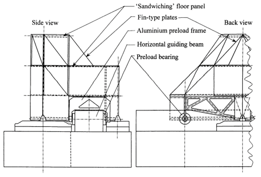 |
| Figure 1. Cross slide structure of a single point diamond turning (SPDT) machine built up from short equilateral triangular tubes, mounted face-to-face and sandwiched between floor panels [3]. |
In fact, for both lightweight and stiff design, it is not the stiffness of every constituent part as such, which is basically important, but more the elastic energy stored per kilogram for every part. It may generally be concluded that parts, both in series or on parallel, which absorb the greater deal of the total elastic energy, should be stiffened at the expense of other parts. Accordingly, the ratio of elastic energy storage to mass as expressed in Equation 1 (see [2], [3]) for each of the parts j can be considered the best indication where improvement, if necessary, is most effective.
$\Large\frac{U_{e,j}}{m_j}=\frac{1}{2}\mu_j\frac{\sigma_{max,j}^{2}}{\rho_jE_j}$
(1)
From this equation it appears that the stiffening of parts with high elastic energy content (to improve the overall structural stiffness) amounts to stiffening of those parts, which are loaded at high (maximum) stress level. If this process of optimization is in steps entirely accomplished, actually a uniform stress distribution within the structure is obtained, and the efficiency parameter µ (see [1]) has reached the optimal value for each of the components.
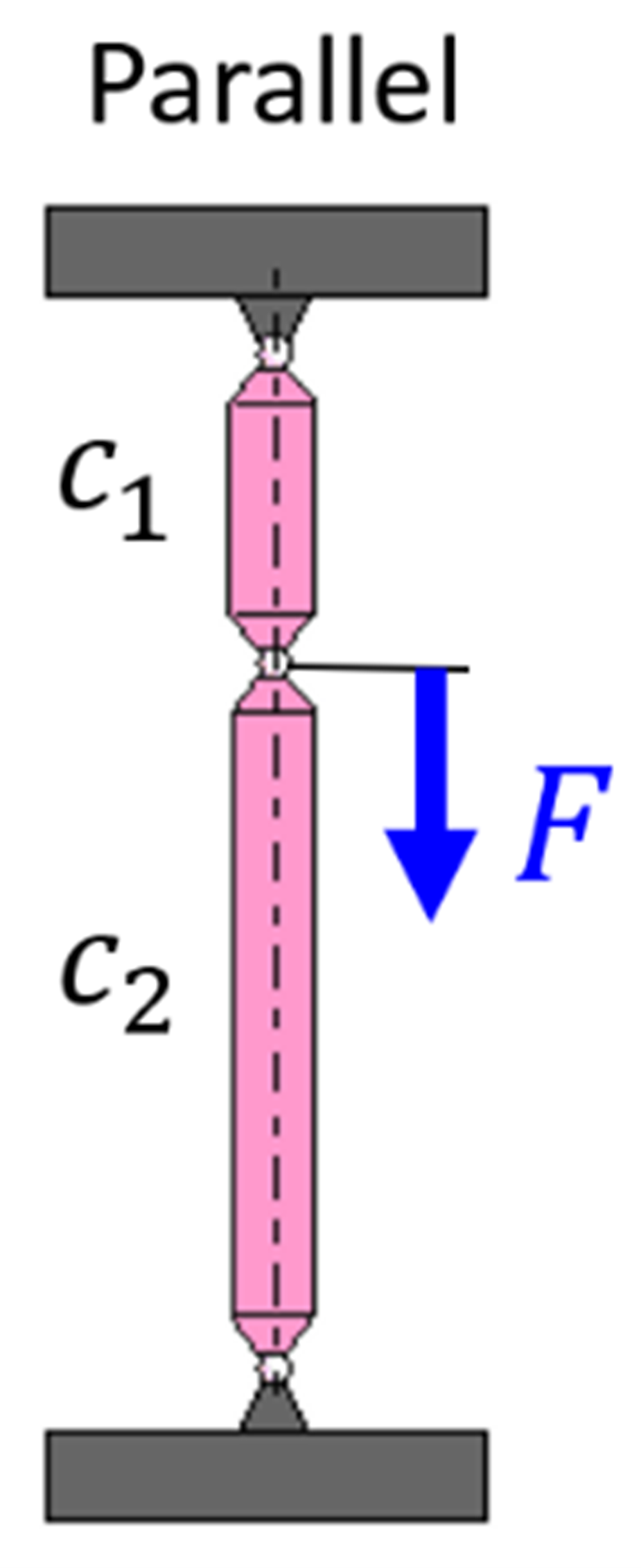 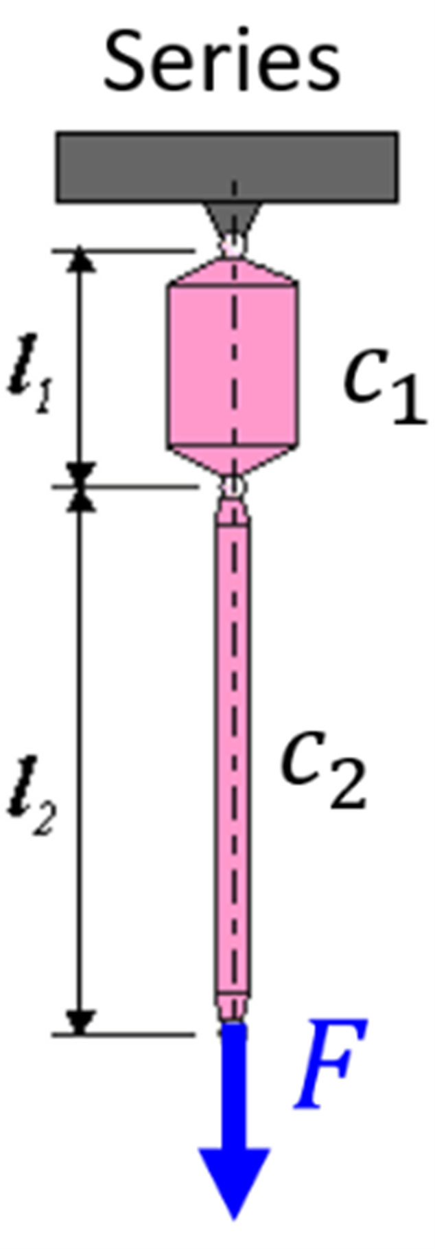 | 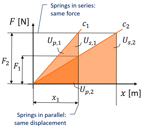 |
| Figure 2. Schematic representation of two parts in parallel (having the same displacement) (left), and parts in series (here carrying the same force) (right). | Figure 3. Elastic energy in a parts with stiffness c1 and c2 that are either placed in parallel (having the same displacement x1) or in series (carrying the same force F2). The larger the surface area underneath the curve, the higher the elastic energy stored. |
Finite element analysis
For analyzing complex plate frame type structures, finite element analysis (FEA) is a most convenient design tool. It allows to easily vary sheet size and thickness, to add different sheets or leave them out, and so to quantify the effect on stiffness, load capacity, mass, and mass moment of inertia gained. Accordingly, the SPDT machine cross slide plate frame structure as shown in Figure 1 was modelled and subjected to linear static stress analyses in FEA. The resulting Von Mises stress distribution and displacements for the optimized cross slide structure are shown in Figure 4. As visible, the stress distribution appears to be quite uniform over the entire structure, indicating maximum stiffness per kilogram.
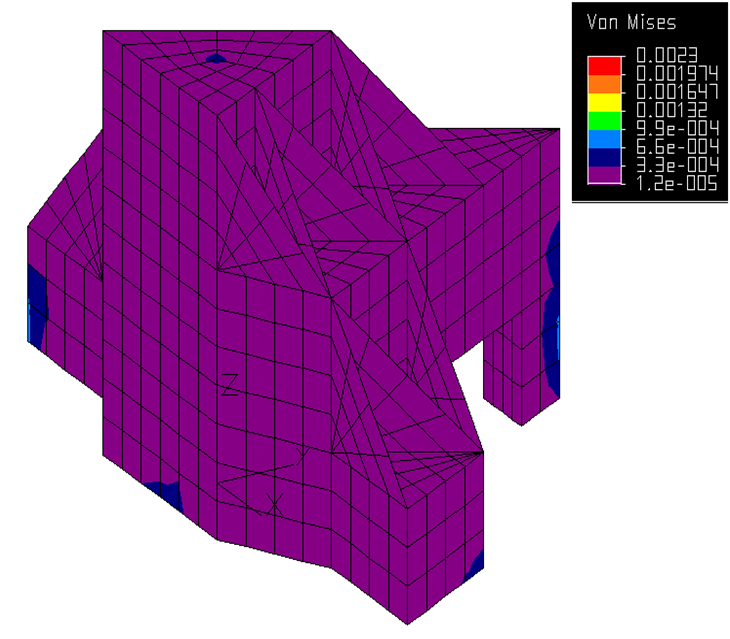 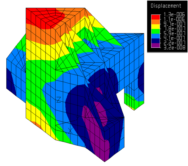 |
| Figure 4. Von Mises stress distribution in [N/mm2] (left) and displacement [mm] (right) from FEA for optimized cross slide structure subject to diamond turning forces of 1 N in x– and y-direction at the tool slide (not shown here). |
 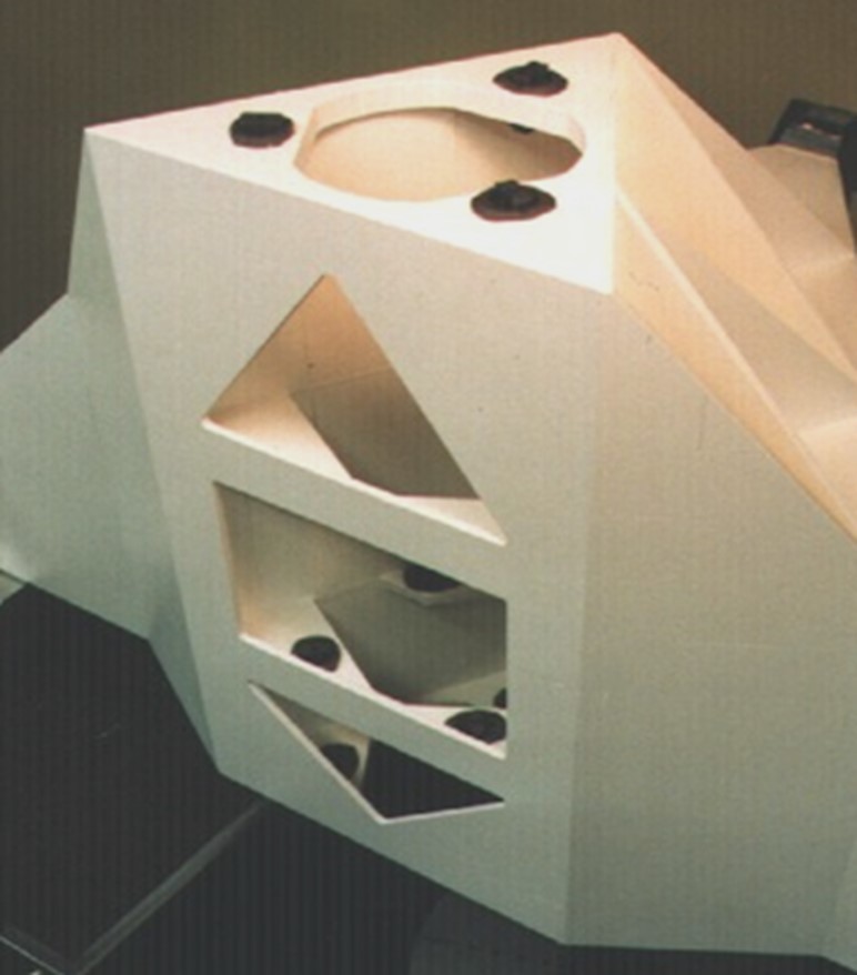  |
| Figure 5. Prototype realization of the SPDT ceramic cross slide structure (left and middle), final machine (right) with sub-micron accuracy and optical surface quality (top) [3], [4], [5]. |
| Application: High-precision single point diamond turning (SPDT) machine | Realized: Prototype SPDT machine with ceramic, plate frame cross slide structure. | Principle: Stiffness optimization of (complex) plate frame structures via stepwise pursuing uniform stress distribution through FEA. |
References
[1] Koster, M.P., Constructieprincipes voor het nauwkeurig bewegen en positioneren (in Dutch), Twente University Press, Enschede, 1998.
[2] Hoek, W. van der, Des duivels prentenboek, Lecture notes (in Dutch), Eindhoven University of Technology, Netherlands, 1985-1989.
[3] Vermeulen, J.P.M.B, Ceramic Optical Diamond Turning Machine, Ph.D. Thesis, Eindhoven University of Technology, ISBN 90-5282-954-3, 1999.
[4] Vermeulen, J.P.M.B., Rosielle, P.C.J.N., Schellekens, P.H.J, Design rules for high stiffness ceramic laminate slide constructions, Structural geometry and material selection, 32nd CIRP International Seminar on Manufacturing Systems, Leuven, Belgium, pp. 135-145, 1999.
[5] Vermeulen, J.P.M.B., Rosielle, P.C.J.N., Schellekens, P.H.J., An advanced ceramic optical diamond turning machine – Design and prototype development, Journal: CIRP Annals – Manufacturing Technology, vol. 49, no. 1, pp. 407-410, 2000.
[6] Janssen, J.D., Over de torsietheorie van Vlasov voor dunwandige rechthoekige kokers, PhD Thesis (in Dutch), Eindhoven University of Technology, Netherlands, 1967.
[7] Hoek, W. van der, Het voorspellen van het dynamisch gedrag en positioneringsnauwkeurigheid van constructies en mechanismen, Lecture notes (in Dutch), Eindhoven University of Technology, Eindhoven, Netherlands, 1962-1986.
[8] Schellekens, P., et al, Design for precision: Current status and trends, Annals of the CIRP, Vol. 47/2, 1998.
Development
Hans Vermeulen, TU/e (1999)