Mitigation of friction-induced hunting limit cycles by a second stage, passive and flexure-based.
Introduction
Contact-based bearings are widely used in positioning mechanisms for their relatively low cost and high support stiffness. However, nonlinear friction effects in rolling of sliding linear guides can limit the positioning performance [1]. Typically an integral action of a PID controller is designed to exceed the friction force of a guide and will try to push the carriage of a linear guide towards a setpoint. However, the stick-slip effect introduces a discontinuity in the friction force, resulting in a sudden transition from standstill to movement. The stick-slip effect can lead to hunting limit cycles, which negatively affect the positioning performance of a servo system [2, 3]. This hunting behavior, also called friction-induced limit cycles, is a result of the combination of a controller with an integral action and a system containing a nonlinear transition between the static friction and smaller dynamic friction, the stick-slip effect [4, 5].
To prevent hunting from occurring in a positioning system, the integral action could be removed from the controller, but a microns to tens of microns steady state position error of the servo system will emerge. Reduction of friction is another option by using aerostatic bearings, but this type of bearing is often not straightforwardly suitable in clean-room environments and significantly increases the cost. An alternative method to decrease the friction in mechanical bearings has been researched by Dong et al. [6], in which high frequency vibrations are exerted on the bearing rail in order to mitigate the undesirable nonlinear friction effects like stick-slip. This method called vibration assisted nano-positioning (VAN), shows a decrease in settling time up to 52% without a significant increase in heat and wear in the system. Introducing vibration into a high-precision positioning system, however, might be unwanted due to parasitic vibrations which might decrease performance. Also the systems becomes more complex. Dong et al. later introduce the Friction Isolator concept [7–10], in which an intentional compliance in one direction is positioned in between the bearing and the end-effector of the system.
Principle
A Friction Isolator is an intended compliance in the actuation direction between the bearing and the end-effector of a system. This passive second stage atop the standard linear stage introduces a smooth force-position relationship close to the setpoint, shown in Figure 1. Experimental results show mitigation of hunting cycles and improved settling times.
Problem description
Many parameters are of influence on the working of a friction isolator, such as the friction isolator compliance and damping, system mass, traveled path, and control parameters. In recent studies [7-10] some of these have been researched, however the influence of these parameters on the hunting behavior and the working of a friction isolator is not always clear and a general guideline on designing a friction isolator is still missing. A practical metric to identify hunting cycles from simulations was missing in literature and is therefore set up in this research [11].
Method
A general design strategy will be presented for a friction isolator system. This strategy is based on a parameter study in combination with simulations, from which it is identified which system parameters influence the hunting behavior. A setup is build to verify the model and showcase the increased settling behavior.
Simulation
The basic system of a friction isolator consists of two masses, which are connected through a compliant joint. The compliance is facilitated by leafsprings. A schematic drawing of this type of system can be seen in Figure 1.
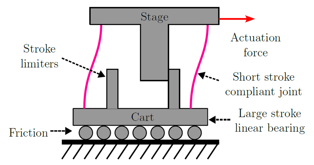
Figure 1: A schematic representation of a friction isolator. The actuation force positions the ’Stage’, which is connected through the compliant joint with the bearing cart. Stroke limiters are used to limit the maximum stroke of the compliant joint.
The effects of friction in controlled systems have been extensively studied in literature, in order to model the friction force. A more complex but computationally doable model is the LuGre friction model [12,13], which is accurate in modeling presliding friction and the stick-slip effect. In the LuGre model, the contact between two bodies at asperities is modeled as contact through elastic bristles. These bristles will deflect like springs when a tangential force is applied, leading to a friction force. If the tangential force is large enough, bristles will start to slip.
A practical metric to identify hunting cycles from a simulation result is not present in literature, therefore one is constructed here. From previous research [4], it can be seen that the hunting cycles have a duration in the order of seconds, with an amplitude in the order of millimeters. A typical example of the position signal of a system affected by hunting can be seen in Figure 3. To find out whether a system shows stable hunting cycles, ie. the system is continuously affected by hunting cycles, the number of peaks in the position signal is counted after 10 seconds. This provides sufficient time for the system to settle and if hunting cycles are observed, it can be stated that the system is affected by stable hunting cycles. The peaks are identified with a minimum time between the peaks of 0.5 seconds and a minimum peak height of 0.1 mm. Each hunting cycle will correspond to one peak. The markers in Figure 5 are an example of the identified peaks in the hunting cycles.
The friction isolator will be controlled by a PID controller. This cross-over frequency determines the bandwidth of the system and with that the response time of the controller.
A parameter study is conducted to find optimal parameters for the friction isolator and to study the effect of multiple parameters on the hunting behaviour. A distinction will be made in this study between the isolated and non-isolated system
In Figure 2, it can be seen that with a higher cross-over frequency, larger than around 20 Hz in this case, no hunting occurs. With a higher cross-over frequency, the controller responds faster which can prevent hunting cycles from occurring.
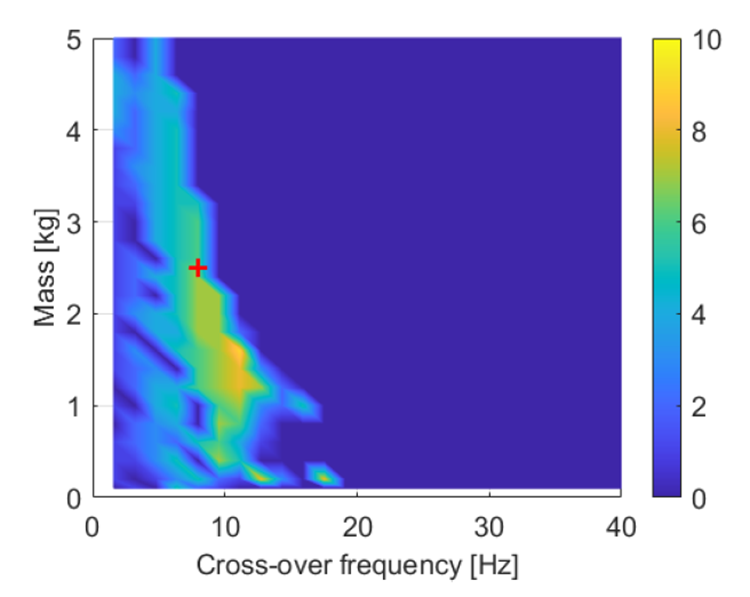
Figure 2. Resulting amount of hunting cycles according to the metric by altering the cross-over frequency and mass. The red marker indicates the evaluation point for the other studies.
In Figure 3, it can be seen that the static friction force has to be significantly larger than the Coulomb friction force in order for hunting to occur. This is logically explained by the stick-slip conditions, in which the static friction has to be larger than the dynamic friction. A larger gap between the static and Coulomb friction force leads to more hunting cycles. At the point of breakaway of the bearing, the control force is therefore also significantly larger than the dynamic friction force resulting in a larger overshoot. Due to a larger error, the proportional part of the controller generates a larger force and the build-up rate of the integral action is increased as well. This results in the breakaway force being reached sooner.
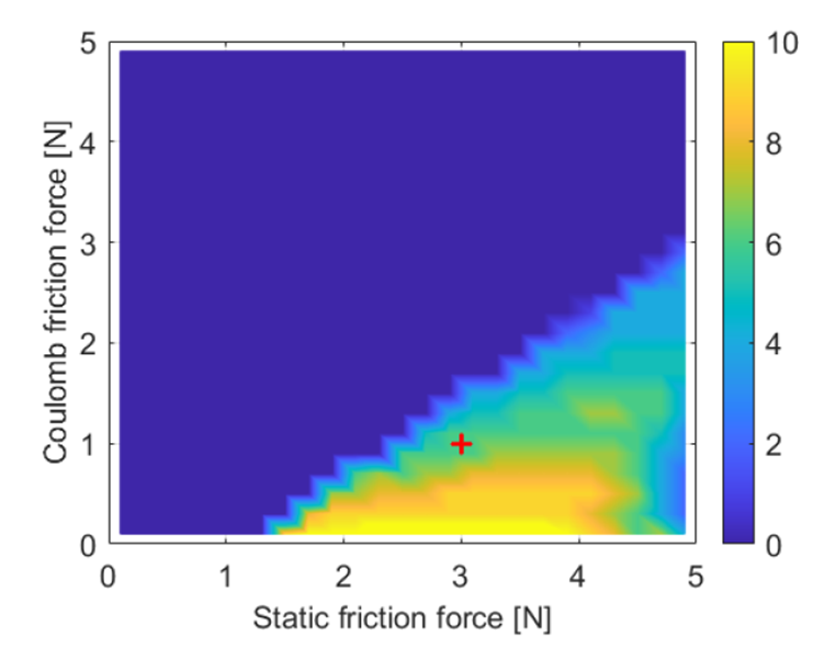
Figure 3: Amount of hunting cycles according to the metric by altering the static and Coulomb friction forces.
Figure 4 shows that the stiffness of the compliant joint should be limited in order for the isolator to work. This is to be expected when taking the principle of the friction isolator into account. At a smaller allowed stroke of the compliant joint, the stiffness of the joint can be higher, since the force applied to the bearing at the maximum stroke is then still smaller than the static friction force.
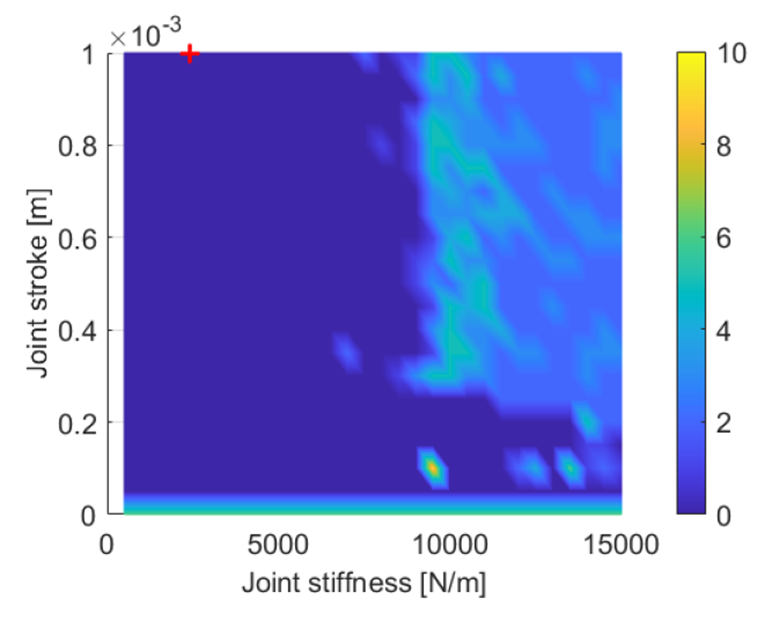
Figure 4. Resulting amount of hunting cycles according to the metric by altering the stroke.
Test setup
A test setup is designed and built to experimentally verify the simulations and design method, shown in Figure 5. Figure 6 shows a typical result of moving the setup over 100 mm, with a prescribed acceleration of 100 m/s2. Results of both the isolated and non-isolated system are plotted in this graph, from which it can be seen that hunting cycles are present in the non-isolated system, while the friction isolator settles to the reference position.
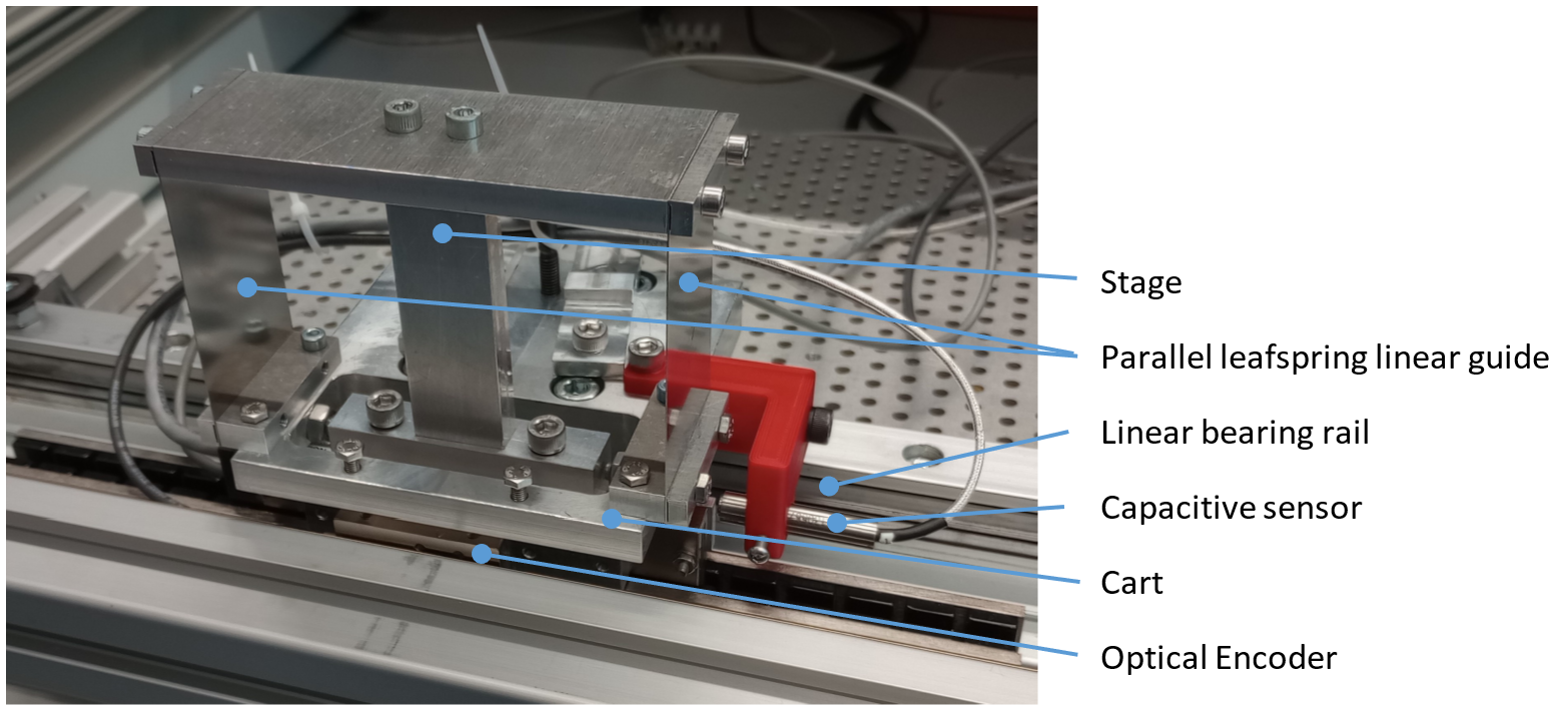
Figure 5. Overview of the test setup.
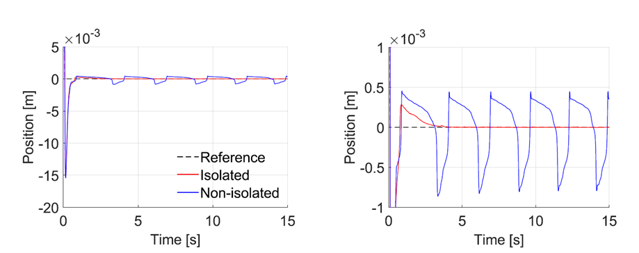
Figure 6: A) Position data of the isolated and non-isolated system after applying a 100 mm step movement, with a prescribed acceleration of 100m/s2, at a controller cross-over frequency of 8Hz. Hunting cycles can be seen for the non-isolated system, while the isolated system settles to the reference position. B) The same graph with a zoomed in position scale.
Conclusion
The performed parameter study on the main parameters of a friction isolator system showed that a limited bandwidth of the applied PID controller and a significant gap between static and dynamic friction forces may result in hunting cycles to occur.
Introducing a compliant joint in a system that suffers from hunting cycles, can prevent these unwanted cycles. It is found that the drive stiffness of this compliant joint should be as low as possible, for the best mitigation of hunting cycles. The design of the compliant joint is limited by the parasitic frequencies that are introduced by this mechanism and the stiffness in supporting directions. The parameter study showed that the friction isolator is a robust method to mitigate hunting cycles against various friction values.
The experimental setup that is built in this research showed mitigation of hunting cycles using a friction isolator for a control bandwidth of only 5 Hz, while the non-isolated system requires a higher bandwidth of 15 Hz. A compliant joint stroke of 0.3 mm is sufficient to prevent hunting from occurring. These experiments verify that the friction isolator is a suitable solution for systems that show hunting behavior.
Developed by University of Twente
- Jasper Fix, Jan de Jong, Dannis Brouwer
Reference
[1] Yoshihiro Maeda and Makoto Iwasaki. Rolling friction model-based analyses and compensation for slow settling response in precise positioning. IEEE Transactions on Industrial Electronics, 60(12), 2013.
[2] Farid Al-Bender and Jan Swevers. Characterization of Friction Force Dynamics. IEEE Control Systems Magazine, 28(6):64–81, 2008.
[3] Henrik Olsson. Control Systems with Friction. PhD thesis, Lund institute of technology, Lund, 1996.
[4] Ron H.A. Hensen and Marinus J.G. Van de Molengraft. Friction induced hunting limit cycles: An event mapping approach. Proceedings of the American Control Conference, 3:2267–2272, 2002.
[5] Ron H.A. Hensen, Marinus J.G. Van de Molengraft, and Maarten Steinbuch. Friction induced hunting limit cycles: A comparison between the LuGre and switch friction model. Automatica, 39(12):2131–2137, 12 2003.
[6] Xin Dong, Deokkyun Yoon, and Chinedum E. Okwudire. A novel approach for mitigating the effects of pre-rolling/pre-sliding friction on the settling time of rolling bearing nanopositioning stages using high frequency vibration. Precision Engineering, 47:375–388, 1 2017.
[7] Xin Dong, Xingjian Liu, Deokkyun Yoon, and Chinedum E. Okwudire. Simple and robust feedforward compensation of quadrant glitches using a compliant joint. CIRP Annals -Manufacturing Technology, 66(1), 2017.
[8] Xin Dong and Chinedum E. Okwudire. An experimental investigation of the effects of the compliant joint method on feedback compensation of pre-sliding/pre-rolling friction. Precision Engineering, 54:81–90, 10 2018.
[9] Xin Dong and Chinedum E. Okwudire. Influence of design parameters on the effectiveness of friction isolators in mitigating pre-motion friction in mechanical bearings. Mechatronics, 71:102444, 11 2020.
[10] Jiamin Wang, Xin Dong, Oumar R. Barry, and Chinedum Okwudire. Friction-induced instability and vibration in a precision motion stage with a friction isolator. JVC/Journal of Vibration and Control, 28(15-16):1879–1893, 8 2022.
[11] Jasper A. Fix. A Linearized Parameter Study Of A Friction Isolator System: Towards A Frequency Domain Design Guideline. MSc. Thesis of Mechanical Engineering, University of Twente, the Netherlands. Aug 2023.
[12] C. Canudas de Wit, P. Lischinsky, K. J. Åström, and H. Olsson. A New Model for Control of Systems with Friction. IEEE Transactions on Automatic Control, 40(3), 1995.
[13] Karl Johan Åström and Carlos Canudas-De-Wit. Revisiting the LuGre Friction Model. IEEE Control Systems, 28(6), 2008.