If the right choice of material and geometry and the proper application of conditioning techniques do not lead to the desired system performance, the last step is to apply compensation techniques.
If it is possible to identify the dominant thermal deformation, it may be possible to compensate for this deformation in the controls (software) of the machine. This is illustrated in Figure 10.A [Pierse, 2006], where a machine tool is shown. When machining a work piece, hot chips and cooling fluids are washing down on the machine base; causing it to deform (bending). This deformation leads to an error (displacement) between cutting tool and work piece. Temperature sensors are placed at the bottom and top of the machine base. The thermal deformation of the machine base can be predicted by determining the relation (sensitivity S) between the measured temperatures (Ttop and Tbottom) and the thermal deformation d.
$$d=S(T_{top} – T_{bottom})$$
| Name | Symbol | Units | Description |
| Distance | d | m | Thermal deformation |
| Sensitivity | S | m/K | |
| Temperature 1 | Ttop | K | Temperature upper sensor |
| Temperature 2 | Tbottom | K | Temperature lower sensor |
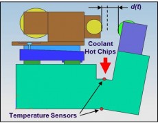
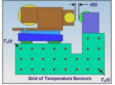
Figure 10.A: Simple thermal compensation
Figure 10.B: Thermal compensation with a grid of temperature sensors
The sensitivity can be determined analytically (modelling) or empirically (measuring). By applying a software correction the control system of the machine tool, based on this relation and the measured temperatures, the thermal induced deformation can be compensated.
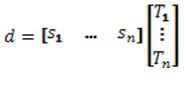
It is not always easy to determine the dominant thermal disturbance or deformation in a machine tool. In many cases, more dominant heat sources are present which influence the thermal stability, such as the drive systems and the environment. In that case, a grid of temperature sensors can be placed on the machine base, as illustrated in Figure 10.B. The relation between the measured temperatures and the thermal deformation of a certain point of interest, for instance between the cutting tool and the work piece, can be expressed in matrix form as:
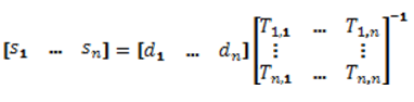
The determination of the sensitivity vector can be done by placing in turn a local heat source on each temperature sensor location. In that case, n different temperature distributions and n different deformations (at the point of interest) are measured. The sensitivity vector can be determined by the relation:
Also in this case, the sensitivity vector can be determined analytically, empirically, or both. The number of temperature sensors can be reduced by removing those sensors with the smallest sensitivity [Ruijl, 2001].
Compensation techniques are more and more applied in precision machines, especially in machine tools and measuring machines. The previous mentioned techniques are some simple examples. More advanced techniques are being developed, such as thermal system identification (e.g. thermal mode shapes). These techniques and the technique above are explained in more detail in [Koevoets, 2007].