Metrology loop – Non-contact measurement machine for freeform optics
The performance of high-precision optical systems using spherical optics is limited by aberrations. By applying aspherical and freeform optics, the geometrical aberrations can be reduced or eliminated while at the same time also reducing the required number of components, the size and the weight of the system. New manufacturing techniques enable creation of high-precision freeform surfaces. Suitable metrology (high accuracy, universal, non-contact, large measurement volume and short measurement time) is key in the manufacturing and application of these surfaces, but in the early 2000s not yet available.
Description
Manufacturing machines are often set up as C-arches, connecting tool and workpiece at the point of interest. The C-arch stiffness is determined by the structural loop, and the C-arch position information by the metrology loop. Typically, these loop (largely) overlap in 3D space, potentially causing measurement errors in the metrology loop (see Figure 1). In high tech systems, loops are preferably separated and assigned to different physical parts of the system in order to minimize uncertainty.
For the non-contact measurement machine for freeform optics [1], a cylindrical scanning configuration is used with an optical distance probe (non-contact, universal and fast). With a probe with 5 m range, circular tracks on freeform surfaces can be measured rapidly with minimal dynamics. By applying a separate metrology frame, relative to which the position of the probe [3] and the product are measured (see Figure 3), most stage errors are eliminated from the metrology loop. Furthermore, because the probe is oriented perpendicular to the aspherical (local) best-fit of the surface, the sensitivity to tangential errors is reduced. This allows for the metrology system to be 2 dimensional.
The metrology system measures the position of the probe relative to the produce in the six critical directions in the plane of motion of the probe (the measurement plane). By focusing a vertical and horizontal interferometer onto the ψ-axis rotor, the displacement of the probe is measured relative to the reference mirrors on the upper metrology frame. Due to the reduced sensitivity in tangential direction at the probe tip, the Abbe criterion (see Design Principle 9) is still satisfied. Silicon carbide is selected for its excellent thermal and mechanical properties. Nanometer-level stability was obtained under the expected thermal load. Simulations on the multi-probe method show capabilities of in process separation of the spindle reference edge profile and spindle error motion with sub-nanometer uncertainty.
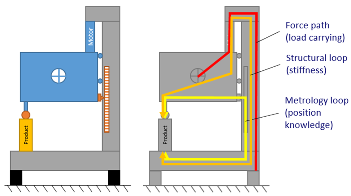 | 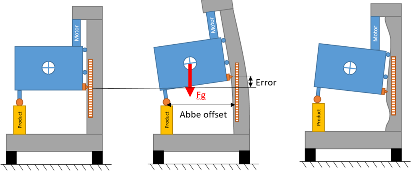 |
| Figure 1. Schematic representation of a traditional manufacturing machine. The structural loop (orange), metrology loop (yellow) and the force path (red) typically coincide, potentially causing measurement errors in the metrology loop [2]. | Figure 2. Error motion in the metrology loop by mechanical or thermal load or manufacturing tolerances results in measurement errors (uncertainties). |
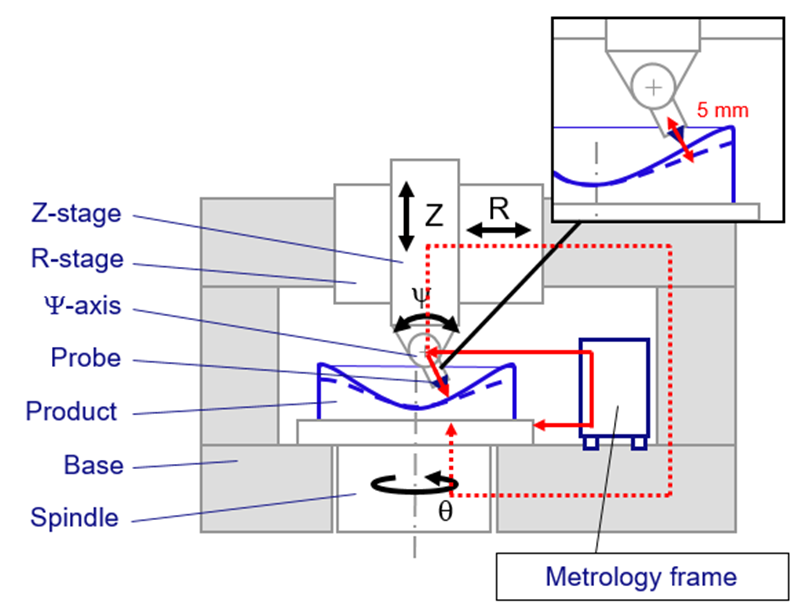 |  |
| Figure 3. Schematic representation of the machine concept that consists of a non-contact, long range optical probe [3], which measures a part that is rotated at a spindle and is moved in a 2D plane by a Z-R motion system. | Figure 4. Full metrology loop based on measurement of 6 critical in-plane, viz. length of the probe, R and Z position of the |
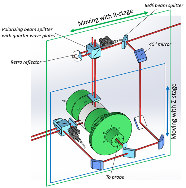 |  |
| Figure 5. Laser interferometer system measuring on | Figure 6. Prototype realization of the non-contact measurement machine for freeform optics [1]. |
Definitions
- Structural loop (= stiffness or position loop):
The assembly chain from one machine element to another, which provides the physical support and constraint for each element - Metrology loop (= measurement loop):
The shortest path that carries information about the relative position of two or more measurement locations and consists of a series of solid objects measurably connected by a position measurement sensor or a calibrated sliding mechanism - Force path (= load path):
The assembly chain from one machine element to another which conducts forces (static and dynamic).
| Application: Non-contact measurement machine for freeform optics | Realized: Prototype system, called NANOMEPHOS, which served as a basis for the NMF platform by Dutch United Instruments. | Principle: Separation of the metrology loop from the structural loop and force path to reduce measurement uncertainty. |
References
[1] Henselmans, R., Non-contact measurement machine for freeform optics, Ph.D. Thesis, Eindhoven University of Technology, The Netherlands, April 2, 2009.
[2] Henselmans, R. Non-contact measurement machine for freeform optics, Lecture notes 4CM50 Application of Design Principles, Eindhoven University of Technology, May, 2021
[3] Cacace, L.A., An optical distance sensor – Tilt robust differential confocal measurement with mm range and nm uncertainty, Ph.D. Thesis, Eindhoven University of Technology, The Netherlands, December 1, 2009.
Development
Rens Henselmans, TU/e, TNO (2009)