Chapter 2 - Design using flexures
Chapter 3 - Design for static stiffness
Chapter 9 - Design for load compensation
Increasing load capacity and support stiffness of flexures by overconstraining
Introduction
Flexure mechanisms allow for highly predictable motion yet often suffer from limited load capacity. To carry a high load, the concept of a large number of flexures in parallel is investigated. The design may then be chosen such that the load also eliminates the drive stiffness by static balance. Increased stress and buckling due to overconstraints can be avoided if the load misalignment and manufacturing tolerances stay within computable bounds. A parallel leafspring mechanism is compared to a mechanism with 23 parallel leafsprings over a stroke of 5 mm in a 200×100×50 mm3 volume. Two specific cases are investigated.
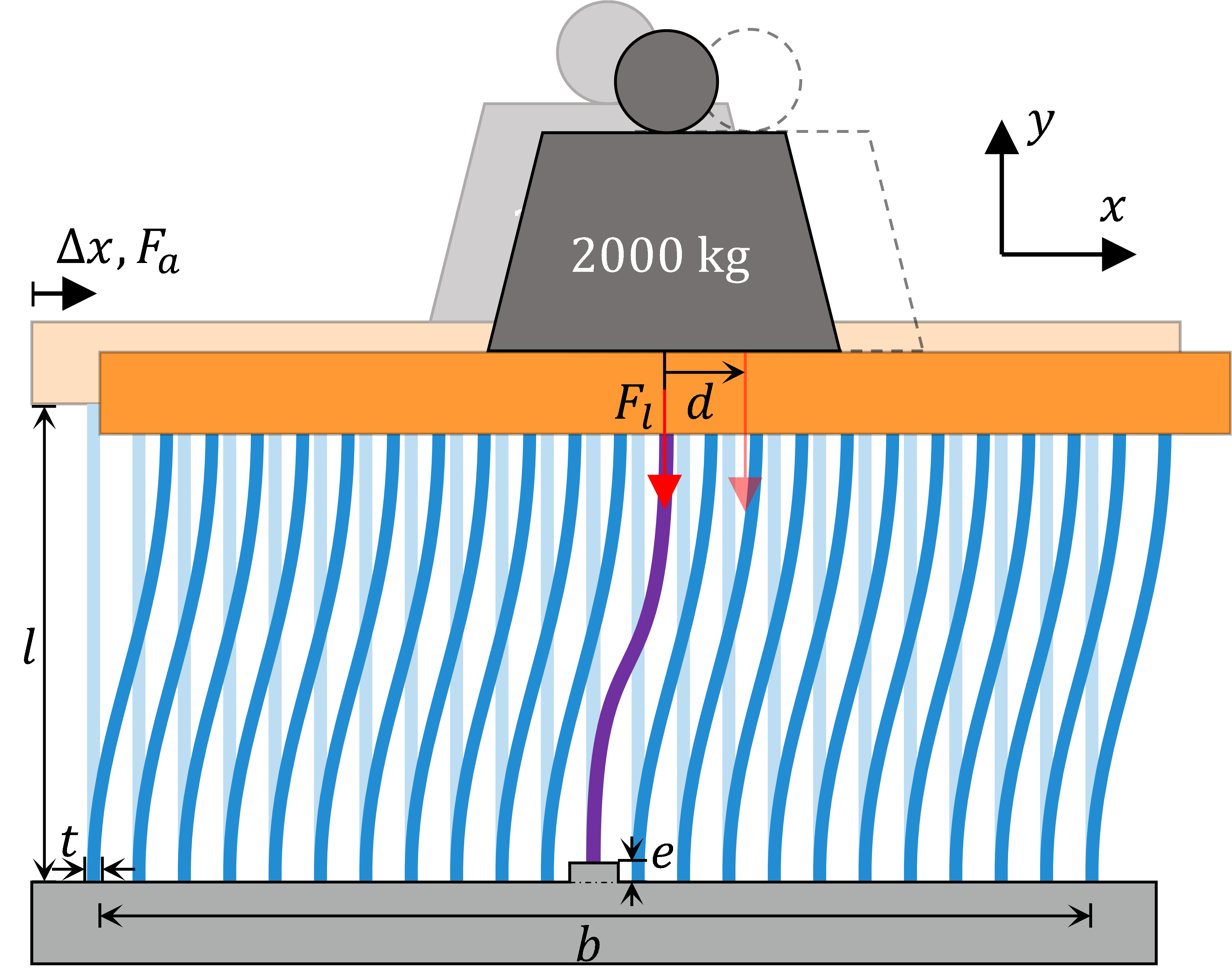
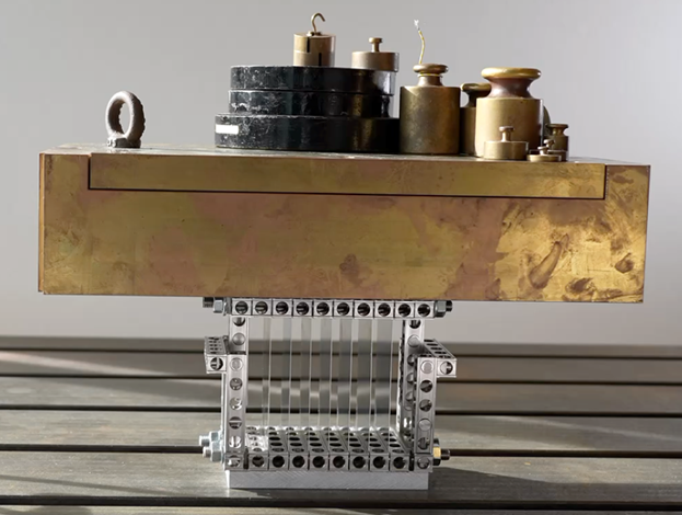
Figure 1. a) A massively overconstrained parallel flexure guidance ($n=23$) supports a large constant preload $F_l$. This load statically balances the mechanism, leading to zero actuation force $F_a$ , b) a photo of the setup.
The overconstrained nature of the design may lead to undesired internal loads due to manufacturing tolerances and thermal gradients. Deleterious consequences include additional stress, binding and unexpected buckling behavior. Previous work [1–3] has shown that these adverse effects may be avoided if the tolerances stay within certain limits. The influence of manufacturing tolerances and thermal gradients may be predicted and controlled, showing that the robustness of the system is maintained as long the tolerances stay within 0.01% of the flexures’ length. Even if one of the flexures buckles, the system as a whole remains stable and able to carry the high load [4].
Case 1: Constant load which is used to preload the flexures
A 23 leafspring mechanism, with similar leafspring length, width, thickness and outer mechanism dimensions, without pretension has a much larger actuation force than a 2 leafspring parallel leafspring mechanism, shown in Table 1. With pretension this actuation force can be reduced, close to zero. There are two important observations:
1) the maximum stress level decreases. This is because the maximum curvature of the deflected leafsprings is a combination resulting from compressive stress and bending stress. The combined shape results in less deformation at the leafspring ends, which lowers the stress there. This is also the location where the stress due to bending alone was maximum [4] [ref ASPE2022].
2) The support stiffness decreases only by 12% by addition of the load. This is because the preload is only 25% of the buckling load. To compare the 23 leafspring mechanism with load with the parallel leafspring mechanism with equal stress level, the thickness of the 23 leafspring mechanism is increased by 24%, which in turn results in a 22% increased support stiffness, and a 42% increased load capacity. Compared to the parallel leafspring mechanism the buckling load would have been exceeded by a factor of 4.1. The support stiffness has increased a factor of 12.1.
Table 1. Constant load leafspring mechanisms with 2 and 23 leafsprings evaluated at a 5mm displacement.
| Parallel leafspring mechanism | 23 leafspring mechanism, no load | 23 leafspring mechanism, with preload | 23 leafspring mechanism, with preload, increased thickness | |
| No. of leafsprings | 2 | 23 | 23 | 23 |
| Leafspring thickness | 1.00 mm | 1.00 mm | 1.00 mm | 1.24 mm |
| Pretension | 0 N | 0 kN | 19.9 kN | 28.2 kN |
| Support stiffness | 0.15 109 N/m | 1.69 109 N/m | 1.49 109 N/m | 1.82 109 N/m |
| Max actuation force | 105 N | 1210 N | 0.8 N | 1.1 N |
| Max stress | 315 MPa | 315 MPa | 279 MPa | 315 MPa |
Case 2: Variable load on top of a preload on the flexures.
A variable load on a parallel leafspring mechanism, a 23 leafspring mechanism and a 23 leafspring mechanism with balancing preload is investigated.
It is important to realize that only a quarter of the buckling load is required to balance the 23 leafspring mechanism, which leaves plenty of support stiffness and variable load. The buckling occurs when the first parasitic vibration mode frequency drops to 0. For a parallel leafspring mechanism with 2 leafsprings this happens with -7kN load this is shown in Table 2 and in Figure 2. With 23 leafsprings the load variation of +/- 7kN changes the first parasitic vibration mode frequency only by 6%, the actuation force does change 430 N, when balanced from -430 to 430 N. The stress of the 23 leafspring mechanisms varies only 8% with a +/- 7kN load variation, and the maximum stress is about 12% lower when a balancing preload is applied. The maximum actuation force reduces by a factor 4.
Overall, the 23 leafspring mechanism with balancing preload and +/- 7kN load variation leaves plenty support stiffness in combination a lowered stress and strongly lowered actuation force.
Table 2. Variable load of half the buckling load (3.5kN) of leafspring mechanisms with 2 and 23 leafsprings evaluated at a 5mm displacement.
| Parallel leafspring mechanism | 23 leafspring mechanism, pretension | 23 leafspring mechanism, with pretension | |
| No. of leafsprings | 2 | 23 | 23 |
| Leafspring thickness | 1.00 mm | 1.00 mm | 1.00 mm |
| Pretension | 0 N | 0 kN | 19.9 kN |
| Variable load | 7 kN | 7kN | 7kN |
| Support stiffness | 0 N/m | 1.62E9 N/m | 1.42E9 N/m |
| Max actuation force | 506 N | 1623 N | 428 N |
| Max stress | 556 MPa | 340 MPa | 292 MPa |
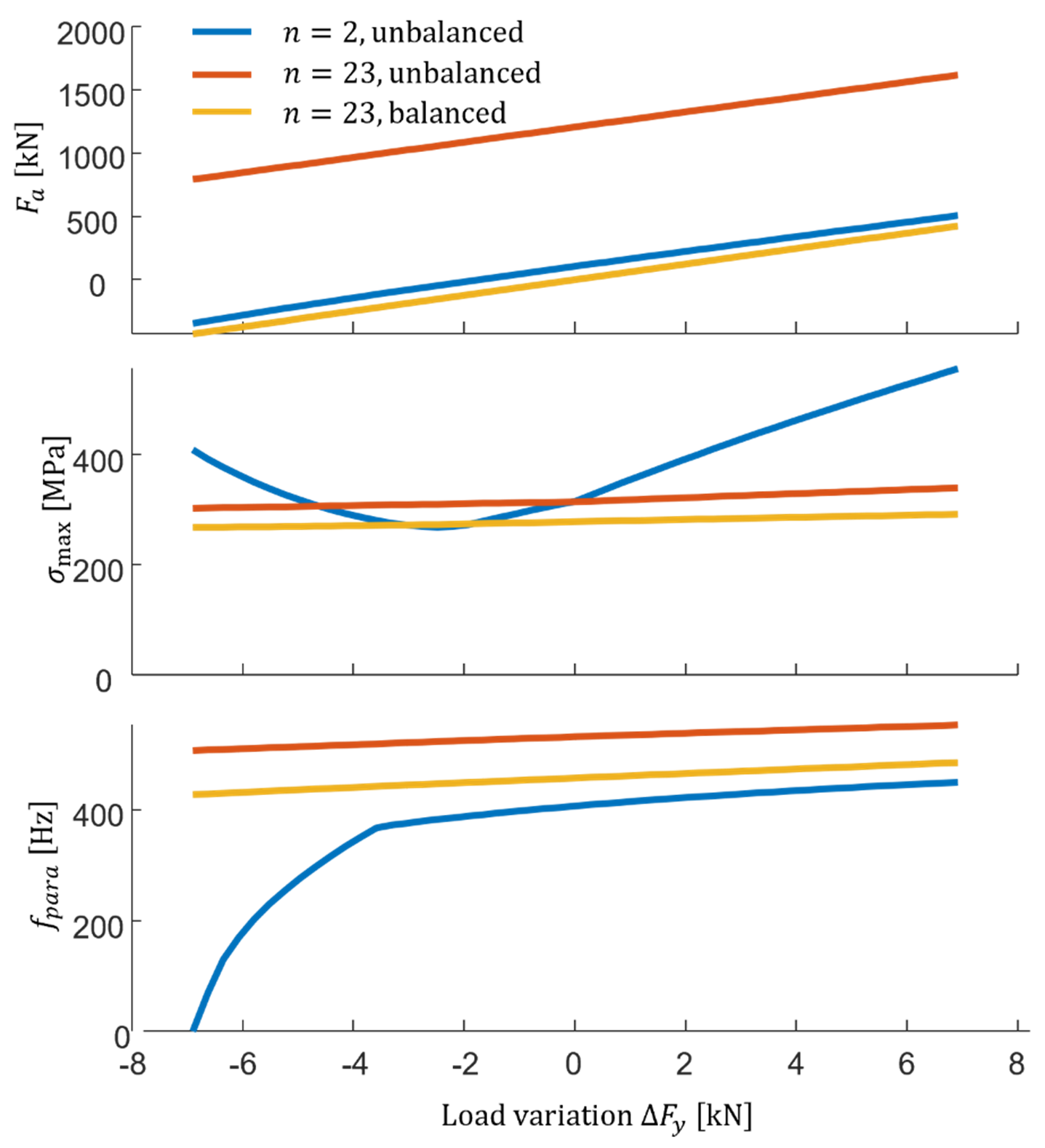
Figure 2. Actuation force $F_a$ , maximum stress $\sigma_{max}$ and the first parasitic vibration mode frequency as a function of the load variation on top of the pretension.
Principle
Flexures in parallel in combination with preload can increase the constant and variable load capacity and support stiffness, at an equal maximum stress level when compared to an exact constraint design, and with an equal or lower actuation force.
Developed by University of Twente
- Jan de Jong, Marijn Nijenhuis, Dannis Brouwer
Reference
[1] S. Awtar, K. Shimotsu, and S. Sen, “Elastic averaging in flexure mechanisms: A three-beam parallelogram flexure case study,” J. Mech. Robot., vol. 2, no. 4, 2010.
[2] J. P. Meijaard, D. M. Brouwer, and J. B. Jonker, “Analytical and experimental investigation of a parallel leaf spring guidance,” Multibody Syst. Dyn., vol. 23, no. 1, pp. 77–97, 2010.
[3] M. Nijenhuis, J. P. Meijaard, and D. M. Brouwer, “Misalignments in an overconstrained flexure mechanism: A cross-hinge stiffness investigation,” Precis. Eng., vol. 62, pp. 181–195, 2020.
[4] de Jong, J. J., Nijenhuis, M., & Brouwer, D. M. (2022). A massively overconstrained and statically balanced flexure mechanism for a 20 kN load capacity. In Proceedings – ASPE 2022 Annual Meeting (pp. 98-101). American Society for Precision Engineering. https://research.utwente.nl/files/297732915/20220725_ExtAbstract_MOPFG_v5_sub.pdf