Tip-tilt mirror mechanism with large dynamic range
Description:
The Field Selector Mechanism (FSM) design consists of a Zerodur mirror, bonded to an Invar 36 mirror support, which is constrained in four degrees of freedom (DOF) by a plate spring and a central strut. The former constrains the two in-plane translational DOF of the mirrorand rotation around the optical axisof the mirror, while the latter constrains the mirror in the optical direction, normal to the mirror surface. The remaining two DOF, the tip and tilt directions, are actuated by two actuators, which are located at the edge of the mirror support and are spaced 90° apart around the mirror normal.
Two spindle drives actuate the mirror, using a stiffness-reduction transmission to increase resolution: when rotating the motor, the nut compresses a soft spring. The soft spring exerts a force against a high stiffness spring, which is connected to the mirror support. As the stiffness ratio between the soft and stiff spring is 1:22, motion of the nut results in a factor 22 smaller motion of the mirror. This principle increases the resolution dramatically, while compromising only slightly in the dynamic behavior of the FSM; the first eigenfrequency of the stiff spring is 135 Hz.
Absolute accuracy is achieved with two differential inductive sensor pairs. Friction in the spindle drive is overcome by creating a local velocity control loop between the spindle drives and the shaft encoders. Accuracy is achieved by using a cascaded low bandwidth control loop with feedback from the inductive sensors.
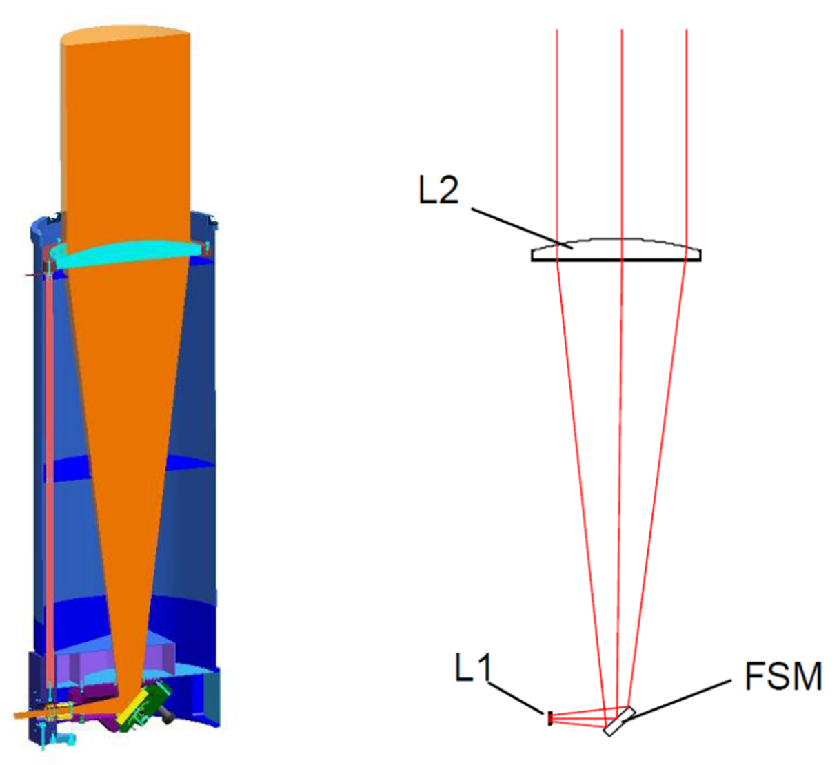
Figure 1 – Left: Cross-sectional CAD drawing of the Optical Tube Assembly (OTA). Right: Optical model of the OTA. The Field Selector Mechanism (FSM) is located between the two lenses (L1 = Ø30 mm and L2 = Ø380 mm) of a Galilean beam expander.

Figure 2 – 3D CAD drawing of the VLT Field Selector Mechanism.
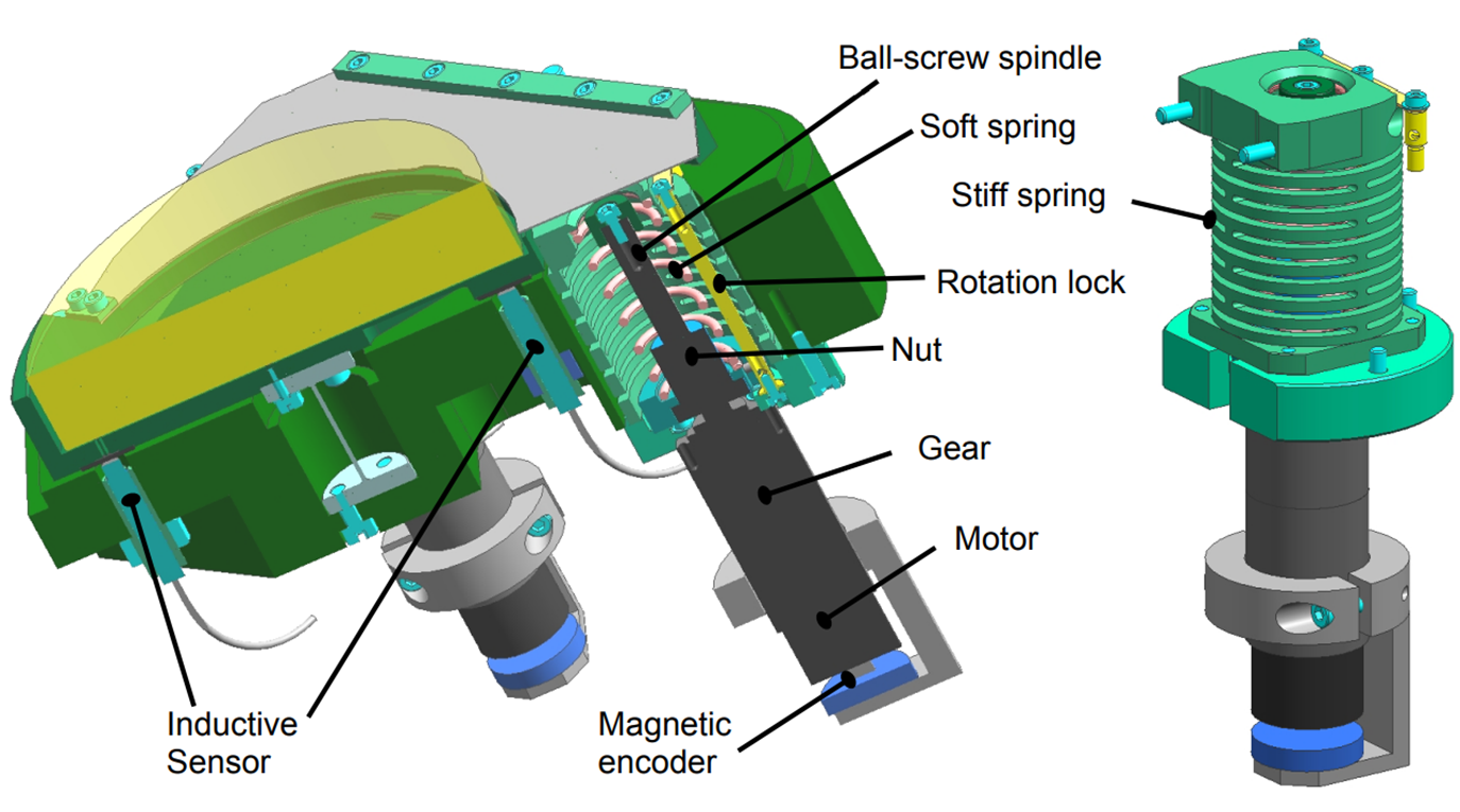
Figure 3 – 3D CAD cut-out of the VLT Field Selector Mechanism, showing left: the inside of the FSM and the custom acutator exerting force on the mirror support and right: the custom actuator singled out.

Figure 4 – VLT Field Selector Mechanism and electronics.
Key Requirements:
- Large mechanical tip-tilt stroke of ±6.1 mrad
- Less than 1.5 µrad (3σ) absolute accuracy
- step response settling time: a 1 arcsec step on-sky in less than 0.2 seconds, corresponding to 21.2 µrad in tip direction and 15.0 µrad in tilt direction.
Note that the absolute accuracy requirement contains dynamic requirements on the pointing jitter of the mirror, as well as on the absolute pointing knowledge with respect to a fixed reference. Furthermore, although the required stroke and step is not equal in tip and tilt direction, the FSM is designed symmetrical such that the largest stroke can be attained in both directions.
Development by TNO Optomechatronics:
- Rens Henselmans, Niek Rijnveld, Bjorn Nijland, Arjo Bos
References:
Rijnveld, N., R. Henselmans, B. Nijland, “A tip/tilt mirror with large dynamic range for the ESO VLT Four Laser Guide Star Facility”, SPIE Optics & Photonics, 2011