Chapter 10 - Design for manufacturability
Conveyor roller, joining shaft to roller
Introduction
A conveyor system is a common piece of mechanical handling equipment that moves materials from one location to another. A belt conveyor generally consists of two or more conveyor rollers a belt and a drive system and is shown in Figure 1. A conveyor roller is commonly supported by bearings with a smaller inner diameter than the roller diameter. A typical and most usual design is the welded roller assembly comprising a small diameter shaft which is assembled straight through the roller using two thin plates, shown in Figure 2. The diameter of the shaft is in the order of the inner diameter of the bearings. Two thin plates are welded to the roller and to the shaft, as shown in Figure 3. There are stiffness and fatigue issues with this assembly. Although the roller is stiff, the plates are not. These allow bending of the relatively long and slender shaft causing compliance, shown in Figure 4. Note that a belt is pretensioned generating cyclic loads on the conveyor roller. In addition, the cyclic loading due to rolling and the strain due to deformation caused by the compliance cause associated fatigue, in particular with respect to the weld with sharp notches, shown in Figure 5.
Alternative
Thicker plates would increase the stiffness of the assembly, but would result in un-used extra mass and cost of the center part of the shaft. In addition, the welded joints at the shaft still suffer from high material stress.
Concept
A high bending stiffness combined with a low mass and low cost is obtained using two small stiff end pieces adhesively bonded to the wide diameter of the roller (see figure 6). The problematic connection of shaft to plate is eliminated by integrating it into a single stiff part. The large diameter connection between the roller and the end pieces can be effortlessly bonded using adhesive. The stiffness is an order of magnitude higher than the welded roller assembly, shown in Figure 7. As a result, reduced stress levels are attained without triggering any fatigue-related concerns.
Principle
Be aware that stiffly joining a small shaft to plate is challenging. Combining the function of small diameter shaft and plate in one part leads to larger stiffness, and avoids notches, stress concentration and fatigue.
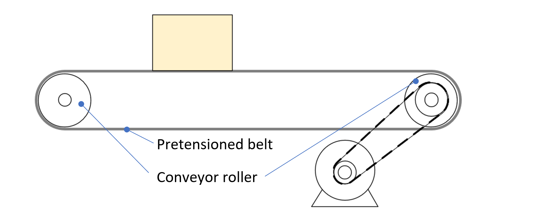
Figure 1. Conveyor with pretensioned belt
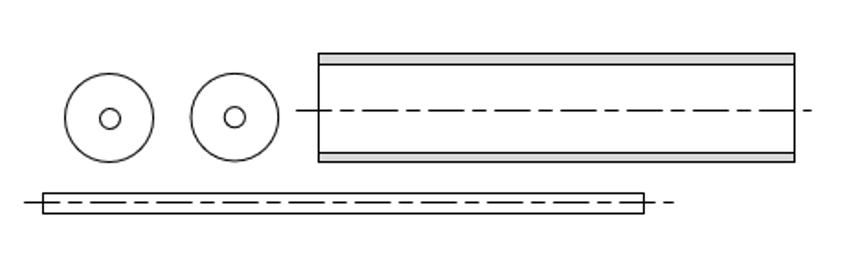
Figure 2. Standard and simple parts used for a welded roller assembly.
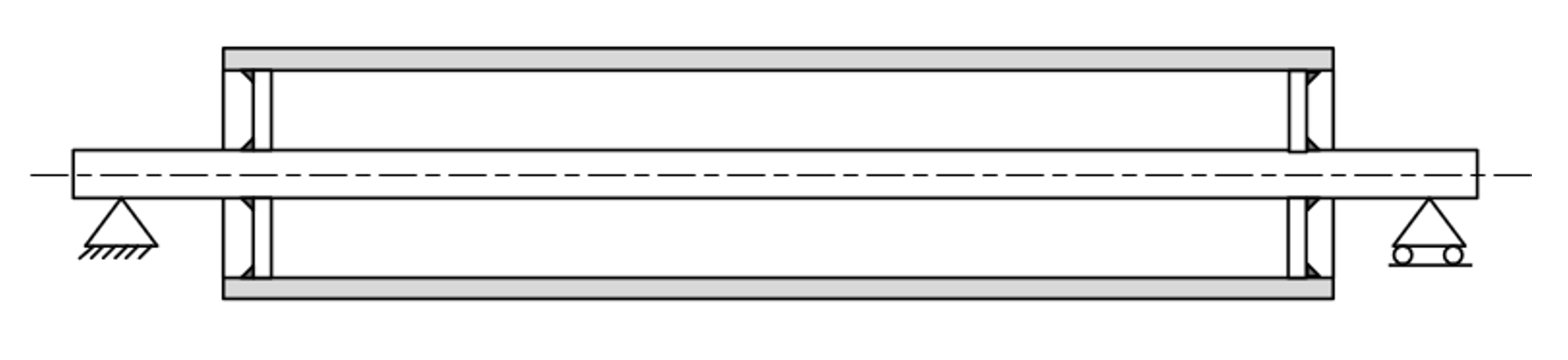
Figure 3. Standard welded roller assembly from simple parts.
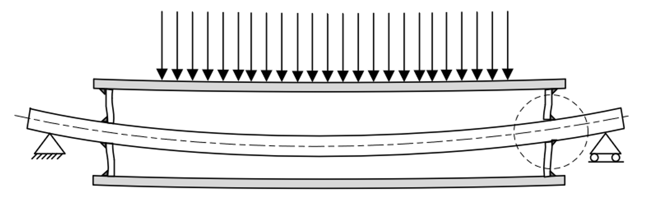
Figure 4. Belt pretension deforms the thin inner shaft. The weld strength is low due to high local stress. The cyclic loading on the rotating roller is a source for fatigue failures.
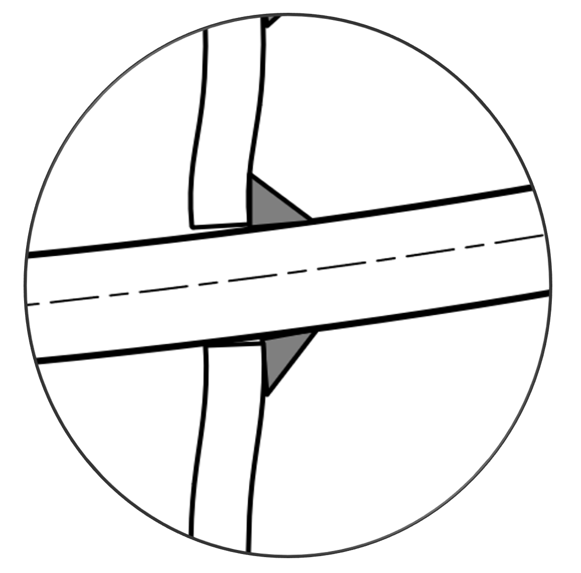
Figure 5. Sharp notches on the interface of plate and weld increase local stresses even further, resulting in low fatigue strength.
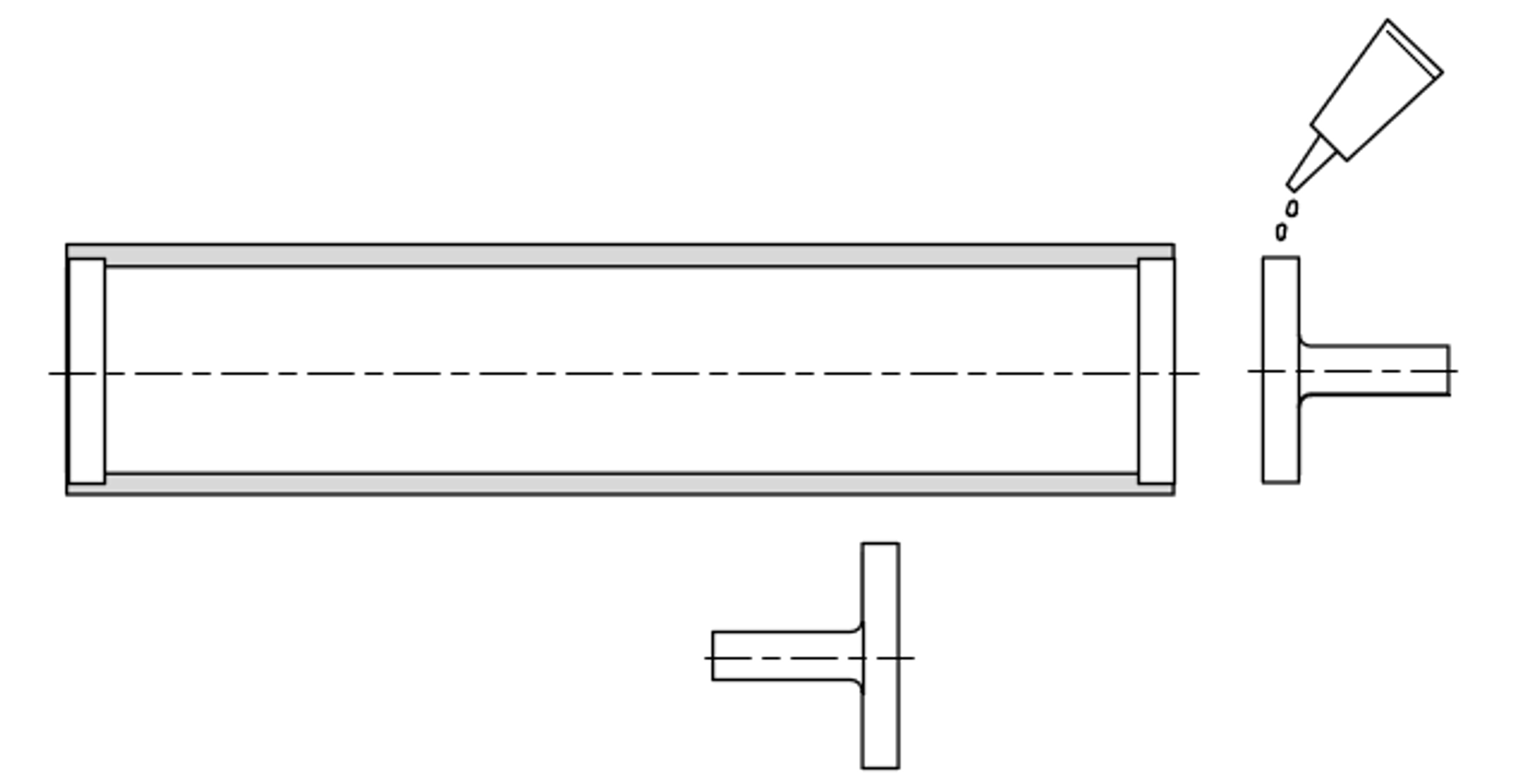
Figure 6. Parts for a low cost, high stiffness and high strength glued roller assembly
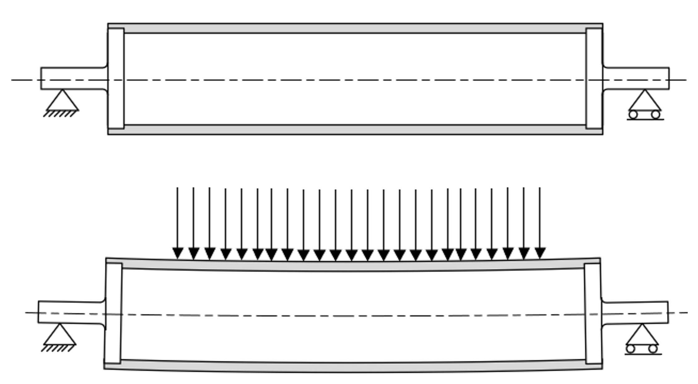
Figure 7. Glued conveyor roller assembly, using stiff and simple end pieces, transferring the load via the stiff outer tube to small diameter smaller bearings. This results in high stiffness and strength at low cost.
Developed by Vanderlande
- Not a specific person