Chapter 2 - Design using flexures
Chapter 3 - Design for static stiffness
5 DOF bike hub force sensor
A bike manufacturer wanted to measure the forces that are introduced into the frame via the wheels. A convenient place for measuring is the hub, because a wheel can be exchanged quickly. Except for the rotational torque all forces needed to be determined. The hub had to remain compact, stiff and strong. The max forces to be measured on a wheel are, 2500 N in vertical direction, 2000 N in horizontal motion direction, 300 N in lateral direction, 100 Nm in roll direction and 50 Nm around the vertical axis. The forces are measured with a repeatability of 0.4% of the full scale range at 100 Hz.
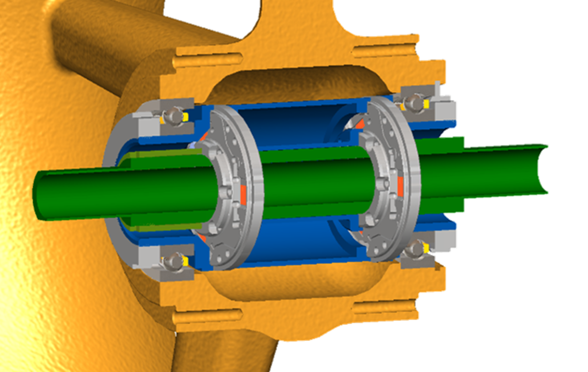
The concept consists of a disc with wire-EDM slots, shown in Figure 1. This creates 3 spokes per disc. The spokes are milled to thin strips on which strain gauges are bonded at both sides, so six per disc. Each spoke is stiff only in the axial direction. There are two discs in the bike hub force sensor, shown in Figure 2. The shaft (green) is inserted through the round hole of each disc and the outer ring is attached to a hub (blue) which is attached to the inner rings of the bearing. The yellow wheel rotates while the bike hub force sensor does not. The compliance and sensitivity in axial direction is higher than in the radial direction. The deformation in axial direction is around 0.02 mm, so a biker does not feel the additional deformation.
 |  |
| Figure 1. Concepts of the slotted disk with three spokes containing strain gauges on both sides. | Figure 2. The hub consists of 2 discs. |
The loads in five directions are discriminated. A vertical radial force results in a common vertical in-plane deformation of both discs. A horizontal radial force results in a common horizontal in-plane deformation of both discs. A moment in the roll direction causes an opposing vertical in-plane deformation of the discs. A moment around the vertical axis causes an opposing horizontal in-plane deformation of the discs. For all the in plane deformations the signal of the strain gauges on both sides of the discs are added. An axial force leads to out of plane bending of the spokes, which is read out by subtraction of the strain gauges of one side in respect to the other.
Braking will cause considerable heat in the system. Strain gauges are sensitive for temperature changes and source fluctuations. Normally a full or half bridge readout is used to compensate temperature influences on the resistance. However, to discriminate all deformation modes the strain gauges needed to be read out individually, so a quarter-bridge circuit was used. To reduce the influence source fluctuations a sinusoidal signal was used with synchronous detection. To reduce temperature influences, the expansion coefficient of the strain gauge was matched to the mating material, and a so called three-wire version of the quarter-bridge circuit was used.
In addition braking will heat the wheel faster than the hub causing temperature gradients in the hub. An expansion of the spokes and gauges will only rotate the wheel slightly in respect to the hub, and will not cause additional large internal forces. An axial expansion difference between the hub and the wheel will cause bending in the spokes and gauges, but this can be detected and compensated for.
The hub sensor has more strain gauges than measuring directions. This means that more measurement information is available than strictly necessary. This has the advantage that with some averaging in the software algorithm, the accuracy and the robustness are increased.
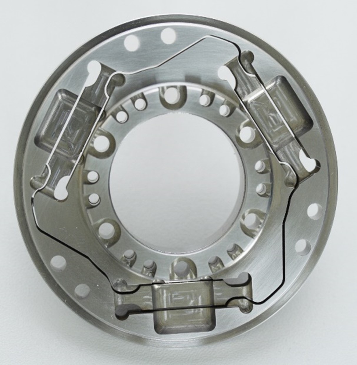 | 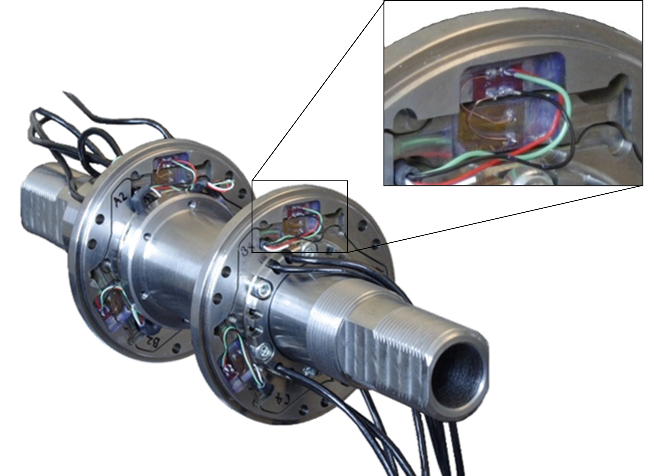 |
| Figure 3. The slotted disk. | Figure 4. The strain gauges are bonded using cyanoacrylate. The adhesive layer must be thin. A strain relief is located next to the strain gauge. |
Principle
Using tuned deformable elements with strain gauges the forces in many directions can be discriminated.
Developed by Demcon
- Hernes Jacobs
Referentie Bron
–