Chapter 2 - Design using flexures
Chapter 3 - Design for static stiffness
Chapter 4 - Design for dynamic stiffness
Chapter 5 - Design for damping
Improved dynamics by overconstraining using viscoelastic material
Introduction
Flexure mechanisms are commonly designed to be exactly constrained to favor determinism, though at the expense of limitations on the maximum parasitic natural frequencies and support stiffness. The use of viscoelastic material is proposed for providing additional support stiffness in a certain frequency range without the indeterminism commonly associated with overconstraining. This design principle of dynamically stiffened exact-constraint design is exemplified by a parallelogram flexure mechanism. The overconstraint and misalignment φ0 in a parallel leafspring mechanism cause stress, shown in Figure 1, and can change the stiffness of the mechanism. Experiments demonstrate that a custom synthesized elastomer compound can compensate for unintended misalignments without significant internal stress buildup, while improving the dynamic performance in terms of a higher first parasitic natural frequency. An analytical investigation clarifies the relationship between misalignment, internal load, stiffness and natural frequency. Using the buckling modes of the system, the nonlinear geometric stiffness is modeled accurately up to the bifurcation. The measurements and analytical model are corroborated by a nonlinear flexible multibody analysis.
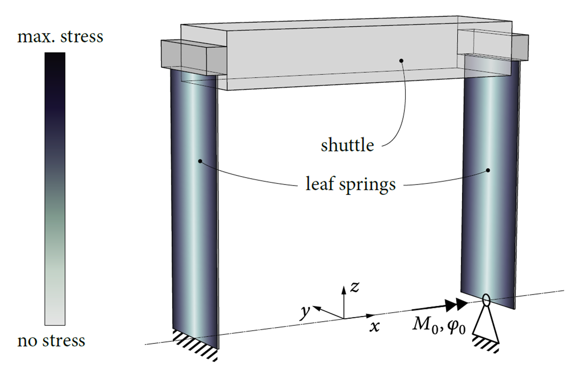
Figure 1. Stress due the overconstraint and misalignment φ0 in a parallel leafspring mechanism.
Principle
To overconstrain a flexure mechanism by means of viscoelastic material. Since the effective stiffness of the viscoelastic material is frequency-dependent, the overconstraint is only present in a designed frequency range. As a consequence, static loads e.g. due to misalignment errors, for which the exactly constrained behavior is desired, hardly affect the mechanism. For dynamic loads, for which the overconstrained behavior is desired, the effective stiffness and the first parasitic natural frequency are higher. This improves aspects such as the control bandwidth and tracking error, and lowers vibration amplitudes. For this purpose a Styrene-Butadiene Rubber is developed with a large ratio between the stiffness at the first parasitic mode, around 100Hz, and the lowest stiffness of the elastomer maximized [1].
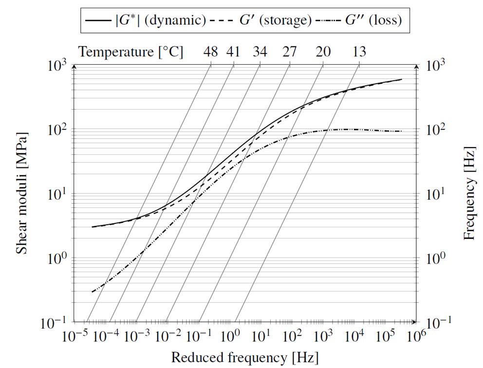
Figure 2. Nomogram for the master curves of the dynamic, storage and loss modulus at a reference temperature of 20 ⁰C. Given a desired frequency on the right side scale, the intersection of a horizontal line with the isotherm of the desired temperature can be determined; by next extending a vertical line from this intersection point down to the horizontal axis, the corresponding reduced frequency is obtained. The shear moduli are plotted as functions of the reduced frequency.
Elastomer compound
The superposed master curves of the shear moduli as a function of the reduced frequency for a reference temperature of 20 degrees Celsius in a nomogram shown in Figure 2. The graph has an additional frequency scale as the ordinate on the right side. That frequency scale can be used with the oblique isotherms to determine the reduced frequency for a given temperature and frequency. This way, the graph encodes the measurement data for a wide range of temperatures and frequencies. The ratio of the dynamic modulus magnitude at 100 Hz to the dynamic modulus magnitude at vanishing frequency is found to be 63 at the operating temperature. This is a measure for the effective stiffness increase that can be obtained at the first parasitic natural frequency of the system by using the viscoelastic material. The relatively high sulfur content and long vulcanisation time that were used have a marked effect on this measure: with a lower sulfur content of 1.5 PHR and a shorter vulcanisation time of 18 minutes, the dynamic modulus ratio is only 16.
Measurement set-up
A schematic of the measurement set-up is shown in Figure 3. It has a screw for controlling the misalignment angle and a dial gauge at the back (not shown) for measuring the misalignment. The base plate, misalignment arm and other frame parts that carry loads are dimensioned such that parasitic compliances are negligible. The leaf springs with support fillets at the ends are made of a single piece of material (Stavax stainless steel, AISI 420) by wire EDM to avoid clamping of the thin leaf springs; the associated strain difference between the clamping blocks and the leaf spring would otherwise lead to micro-slip hysteresis. The leaf springs have a nominal length of 100 mm, width of 20 mm, and thickness of 0.35 mm. Young’s modulus is 200 GPa, the Poisson ratio is 0.29 and the density is 7800 kg/m3. The left notch hinge serves as the flexure hinge that can remove the redundant constraint. The right notch hinge serves to guide the misalignment arm. The new viscoelastic redundant constraint is placed in parallel with the left notch hinge. The first natural frequency of the system, corresponding to a mode in which the shuttle moves in its degree of freedom, serves as a measure of the misalignment sensitivity of the system, since it is affected strongly by the internal load that develops in the overconstrained case. The first natural frequency is measured by a laser displacement sensor. The second natural frequency of the system, corresponding to a mode in which the shuttle moves largely in the y-direction of Fig. 6.2, is the performance-limiting first parasitic natural frequency. It is measured by accelerometers (not shown) on the shuttle. For measurement of the second natural frequency, excessive motion of the shuttle in the degree of freedom is avoided by means of an additional wire constraint (which does not introduce any significant stiffness in the measurement direction). A photograph of the measurement set-up is shown in Figure 4.
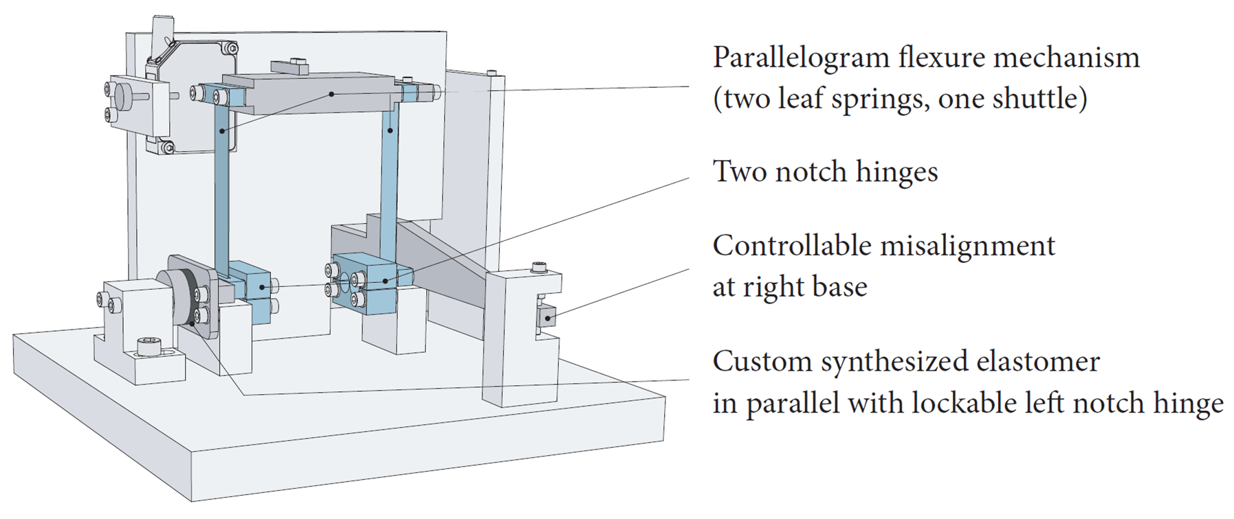
Figure 3. Schematic representation of the measurement set-up.
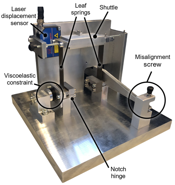
Figure 4: Photograph of the measurement set-up.
Measurements first natural frequency
Shown in Figure 5 are the measurements (solid lines) and simulations (dashed lines) of the first natural frequency (motion in compliant x-direction) for the overconstrained case, the exactly constrained case and the new dynamically stiffened exactly constrained case. The dynamically stiffened exactly constrained case closely resembles the tolerance for misalignment of the exactly constrained case.
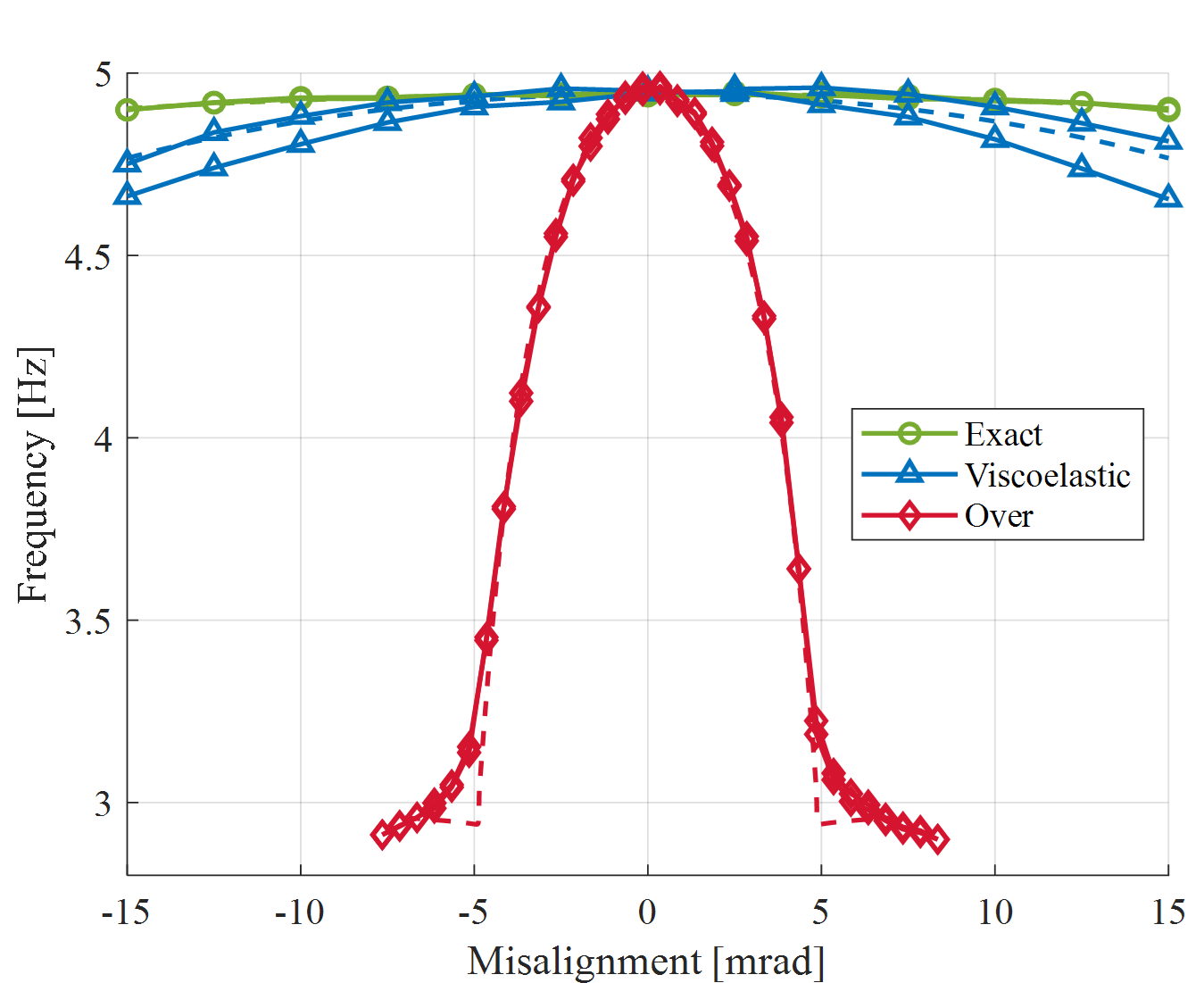
Figure 5: Measurements (solid lines) and simulations (dashed lines) of the first natural frequency for the overconstrained case, the exactly constrained case and the new dynamically stiffened exactly constrained case.
Measurements second natural frequency
Shown in Figure 6 are the measurements (solid lines) and simulations (dashed lines) of the second natural frequency (associated with support stiffness) for the overconstrained case, the exactly constrained case and the new dynamically stiffened exactly constrained case. The dynamically stiffened exactly constrained case closely resembles the high frequency of the overconstrained case.
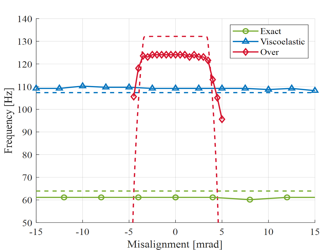
Figure 6: Measurements (solid lines) and simulations (dashed lines) of the first natural frequency for the overconstrained case, the exactly constrained case and the new dynamically stiffened exactly constrained case.
Developed by University of Twente
- Sven Klein Avink, Marijn Nijenhuis, Dannis Brouwer
Referentie Bron
[1] Nijenhuis, M., Klein Avink, S. T. B. , Dierkes, W. K. , Noordermeer, J. W. M. , & Brouwer, D. M. (2020). Improved dynamic performance in flexure mechanisms by overconstraining using viscoelastic material. Precision engineering, 63, 115-125. https://doi.org/10.1016/j.precisioneng.2020.02.002
[2] Klein Avink, S. , Nijenhuis, M. , Dierkes, W. , Noordermeer, J. , & Brouwer, D. (2019). Flexure mechanism with increased dynamic performance by overconstraining using viscoelastic material. In C. Nisbet, R. K. Leach, D. Billington, & D. Phillips (Eds.), European Society for Precision Engineering and Nanotechnology, Conference Proceedings – 19th International Conference and Exhibition, EUSPEN 2019 (pp. 82-85). EUSPEN.