Active vibration isolation system for cryogenic conditions
One of the key challenges for the Einstein Telescope (ET), which is the targeted underground infrastructure to host a third-generation gravitational wave observatory [1], is to create a greatly improved sensitivity. In addition to an increased interferometer arm length of 10 km, a cryogenic system to cool the main optics down to 10-20 K and an advanced vibration isolation system are required to achieve this sensitivity. The problem with commercially available cryo coolers is the large noise level that is generated due to the cooling process, aside from the seismic noise that is entering the system. Therefore, a compact active vibration isolation system was developed as single DoF building block for a multi-DoF system.
Description
The concept is based on a reference mass or inertial mass (seismometer) mounted on top of the isolated mass (see Figure 1), which was earlier proposed and investigated by the Joint Institute for Laboratory Astrophysics for a single DoF [2]. Instead of using helicoil springs with inherent low-frequency internal mode shapes and accurate temperature control for obtaining constant shear modulus at room temperature, a monolithic flexure based straight guide mechanism was designed, both for the isolated mass and the inertial (sensor) mass [3, 4].
  |
| Figure 1. Dynamic concept of the cryogenic active vibration isolation system consisting of an isolated mass, and an inertial (sensor) mass (left), and schematic representation of isolator and sensor module with integrated adjustable gravity compensation mechanisms (right). |
The concept of using a reference mass, but instead, mounted on the ‘floor’ next to the isolated mass as described in [5], allows for rather similar transmissibility and compliancy behavior as also here, functions are split. Realizing sub 1 Hz resonance frequency for the reference mass, however, was deemed problematic within imposed mass (volume) and manufacturing limitations (<10 N/m for 0.2 kg reference mass), and so was the potential for creating sufficient (passive) damping in cryogenic conditions, and therefore, the ‘stacked’ concept was pursued here.
By accurately measuring the relative displacement between the two masses with a (compact) laser interferometer, an estimation is obtained for the absolute acceleration at low frequencies, and the absolute displacement of the isolated mass for frequencies above the decoupling frequency of the sensor or reference mass (4 Hz, see Figure 2). By using the relative displacement as input for a feedback loop with a cryogenic voice coil actuator (CVCA), the open loop (passive) isolation frequency could theoretically be improved from 4 Hz (and 8 Hz) with very little damping to 0.4 Hz with a large amount of damping as shown in Figure 3.
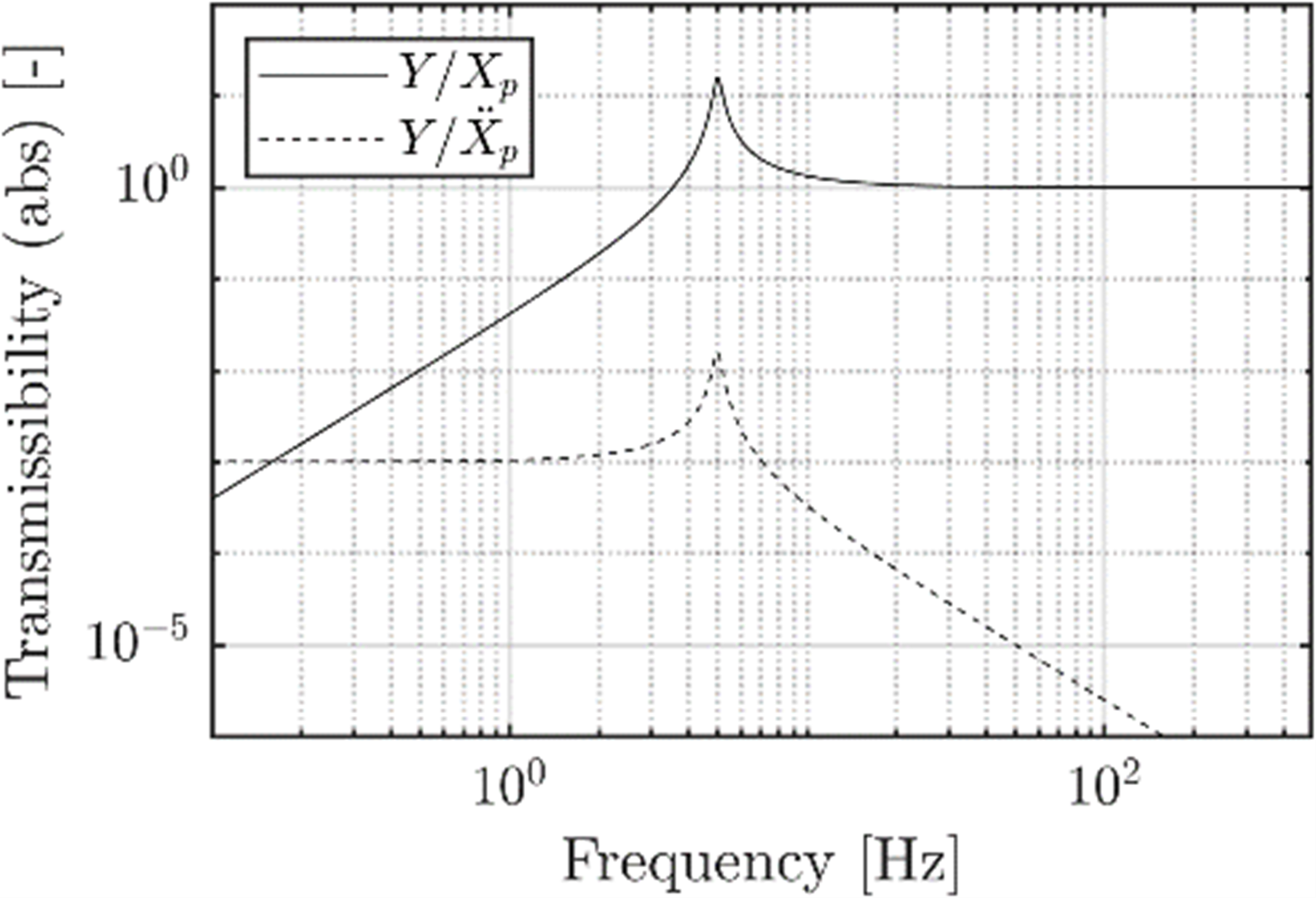 | 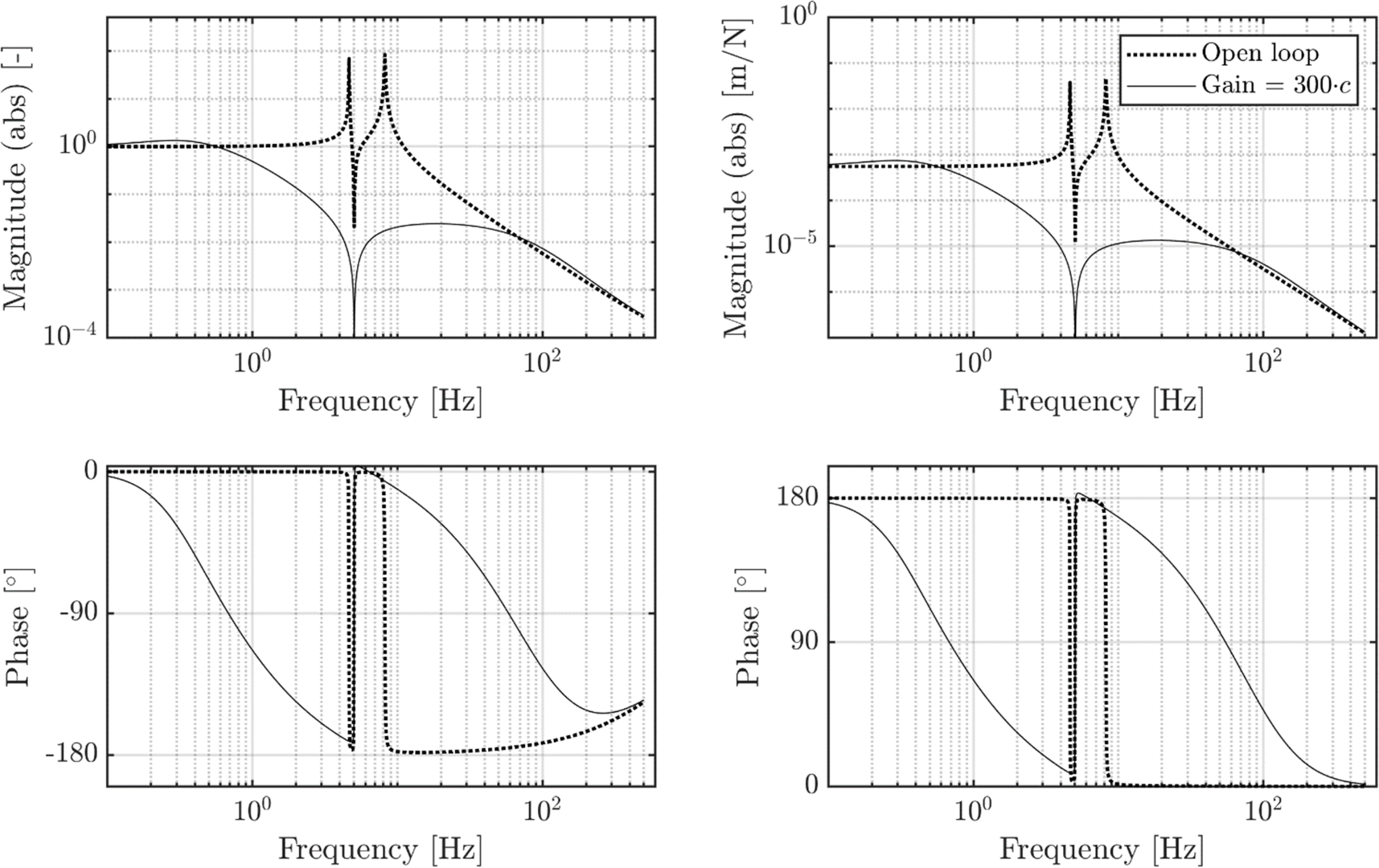 |
| Figure 2. Modelled transmissibility from payload mass displacement $X_p$ and acceleration$\ddot{X}_p$ to relative displacement $Y$ between the two masses. | Figure 3. Modelled transmissibility from floor displacement to payload mass displacement $X_p/X_f$ (left), and Compliance from disturbance force at the payload to the payload displacement $X_d/F_d$ (right), both in open loop (dashed) and closed loop (solid). |
For the single DoF vibration isolator, a monolithic linear straight guide mechanism was designed for ±1 mm stroke based on 6 tangential struts (for symmetry), both for the isolated mass (see Figure 4) and the sensor mass. The former was made out of aluminum 6082-T6 for high thermal conductivity (small gradients) and being applied commonly in UHV and cryogenic conditions, the latter out of phosphor bronze CuSn8P R450 for its high density (small volume), high thermal conductivity, and relatively high fatigue and yield stress. To be compatible to any orientation, an adjustable magnetic gravity compensation (MGC) mechanism was applied with negative stiffness for compensating the stiffness of the elastic straight guide, consisting of 3 sets (120 deg. symmetry) of 3 magnets (see Figure 5). For upward and downward displacement of the sensor mass, the lower and upper outer magnets resp. create an attracting (helping) force towards the inner stationary magnet, resulting in a compensation force for the elastic spring force. Gravity compensation is set by placing the inner magnet at an offset in axial direction. Figure 6 and 7 show the design of the compact cryogenic vibration isolator in exploded view, and the realized prototype resp. both in horizontal position.
 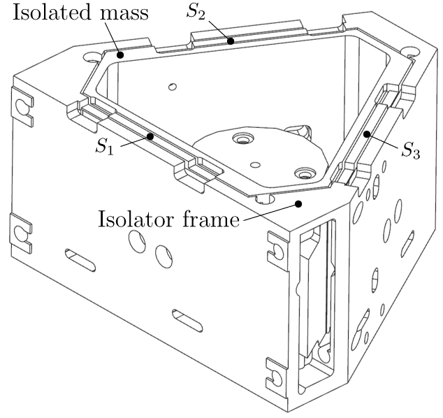 | 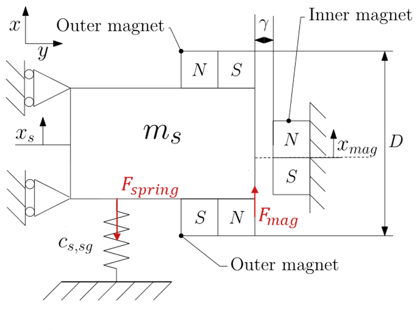 |
| Figure 4. Straight guide mechanism for the isolated mass, also used for the reference mass: Schematic representation (left) and CAD design (right). Upper struts S1-3 are visible at the top. | Figure 5. Schematic representation of the contactless sensor mass MGC with negative stiffness, consisting of 3 sets (120 deg. symmetry) of 3 magnets (1 set shown). |
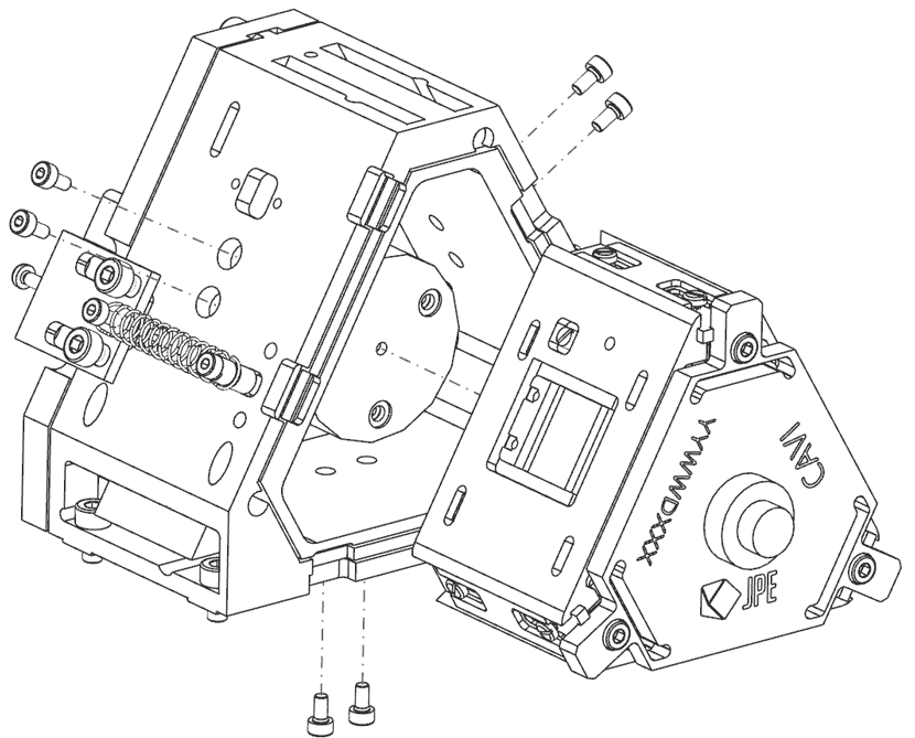 | 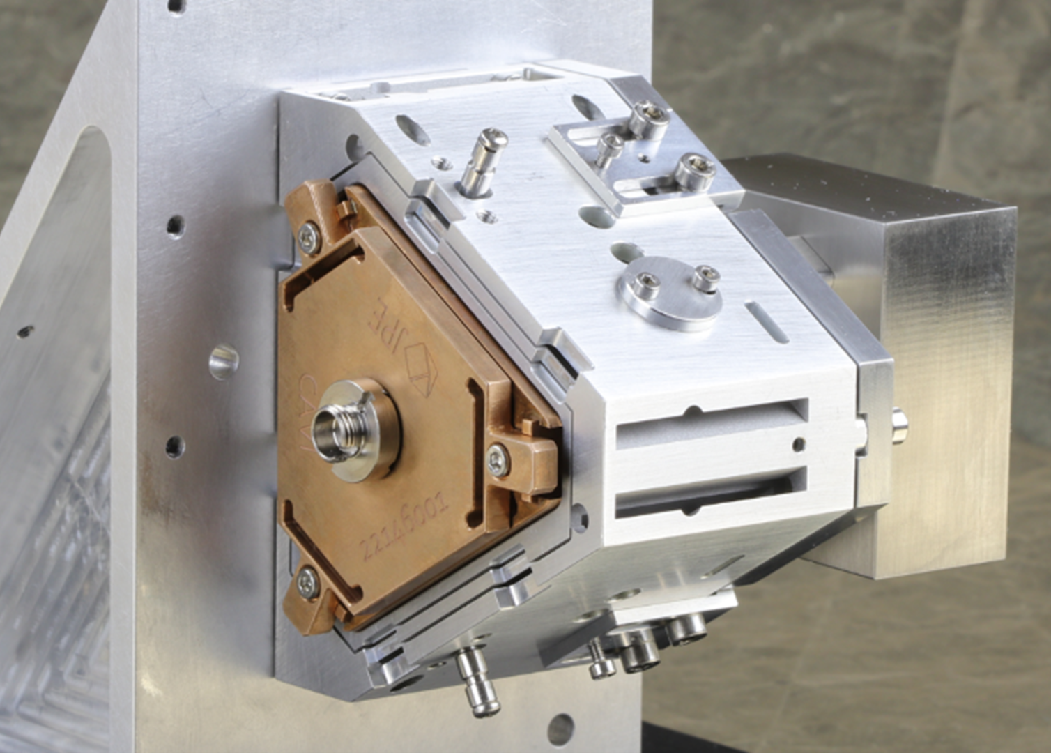 |
| Figure 6. Exploded view of the vibration isolator with isolated mass incl. Lorentz actuator (left), and sensor (reference) mass (right). | Figure 7. Realized prototype of the cryogenic compact vibration isolator: the isolated mass is made out of aluminum 6082-T6, the sensor mass out of phosphor bronze CuSn8P R450. |
After assembly, the plant transfer function from the actuator force Fa to the relative displacement $Y$ was identified. Next, a controller was tuned using a proportional gain, and a lead and a lag filter for stability. Figure 8 shows the measured open loop transfer function, and the transmissibility with and without controller. The chosen controller results in a first effective resonance frequency of the closed loop system at 0.4 Hz, a bandwidth at 100 Hz and a significant amount of damping at the mechanical resonances. The transmissibility graph shows favorable additional attenuation between 0.5 and 50 Hz compared to the mechanics. At 2 Hz, the magnitude $X_p/X_f$ is approximately 0.07, which implies an attenuation of vibrations from the cryo cooler of a factor 14.
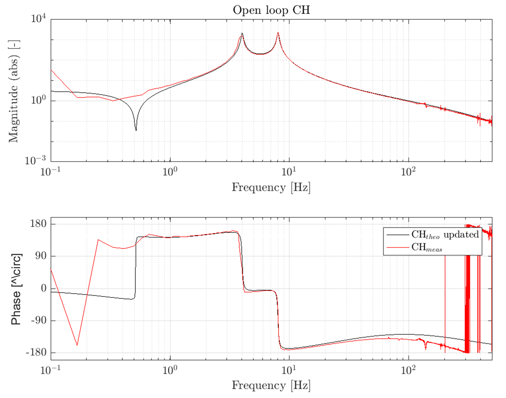 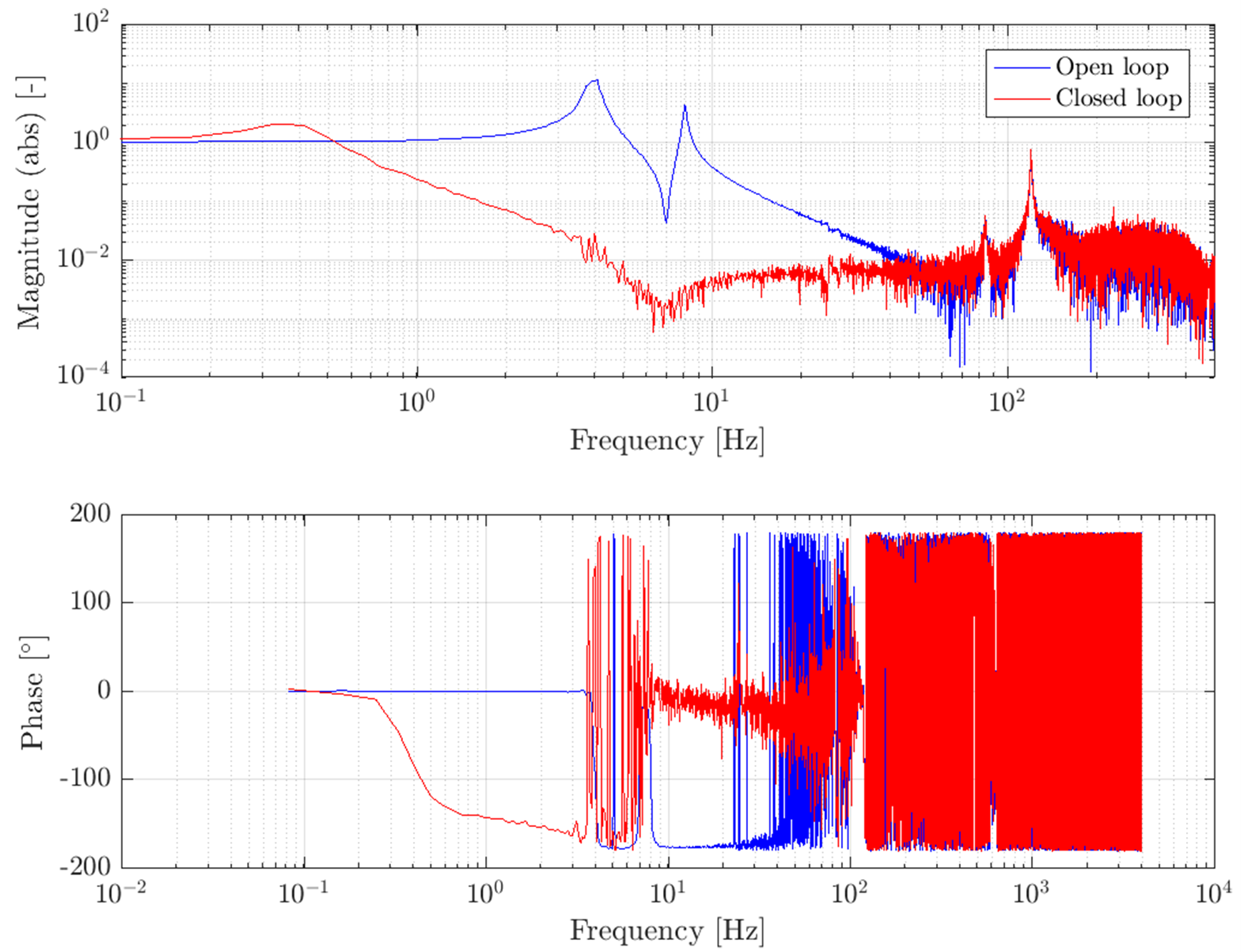 |
| Figure 8. Measured open loop transfer function $Y/F_a$ (left) and transmissibility both in open loop and closed loop situation (right). The transmissibility graph shows a favorable additional attenuation between 0.5 and 50 Hz compared to the open loop mechanics. At 2 Hz an attenuation by a factor 14 is obtained. |
| Application: Vibration isolator for cryogenic conditions. | Realized: Prototype of a compact active vibration isolation system as a single DoF building block for a multi-DoF system, which can be applied in any orientation. | Principle: Active vibration isolation based on a reference mass on top of the isolation mass. |
References
[1] http://www.et-gw.eu/ET (et-gw.eu).
[2] Nelson, P.G., An active vibration isolation system for inertial reference and precision measurement, Review of Scientific Instruments, vol. 62, no. 9, pp. 2069-2075, 1991.
[3] Struver, D.P.P., Design of a voice coil actuated active vibration isolator for cryogenic conditions, Master thesis, Eindhoven University of Technology, Netherlands, 2022.
[4] Struver, D.P.P., Janssen, H.L.M.M., Bree, B.C.T. van, Vermeulen, J.P.M.B., Development of a compact active vibration isolator for cryogenic conditions, 2nd euspen Special Interest Group (SIG) on Precision Motion Systems & Control, ‘s Hertogenbosch, November 15-16, 2022.
[5] Vervoordeldonk, M. J., Ruijl, T. A., Rijs, R. M., Development of a novel active isolation concept, ASPE Spring Topical Meeting on Control of Precision Systems, Cambridge, MA, 2004.
Development
Dennis Struver, TU/e and JPE (2022)