Chapter 2 - Design using flexures
Chapter 3 - Design for static stiffness
Chapter 4 - Design for dynamic stiffness
Exact Constraint Design of a Two-Degree of Freedom Flexure-Based Mechanism
An exact constraint design of a two degrees of freedom cross-flexure-based stage that combines a large workspace to footprint ratio with high vibration mode frequencies is presented. To maximize unwanted vibration mode frequencies the mechanism is an assembly of optimized parts. To ensure a deterministic behavior the assembled mechanism is made exactly constrained. The kinematics of the mechanism are analyzed using methods (1) opening the kinematic loops and (2) Grüblers criterion. Nine release-flexures are implemented to obtain an exact constraint design. Measurements of the actuation force and natural frequency show no bifurcation, and load stiffening is minimized, even though there are various errors causing nonlinearity. Misalignment of the exact constraint designs does not lead to large stress. It can be concluded that designing an assembled mechanism in an exactly constrained manner leads to predictable stiffnesses and modal frequencies.
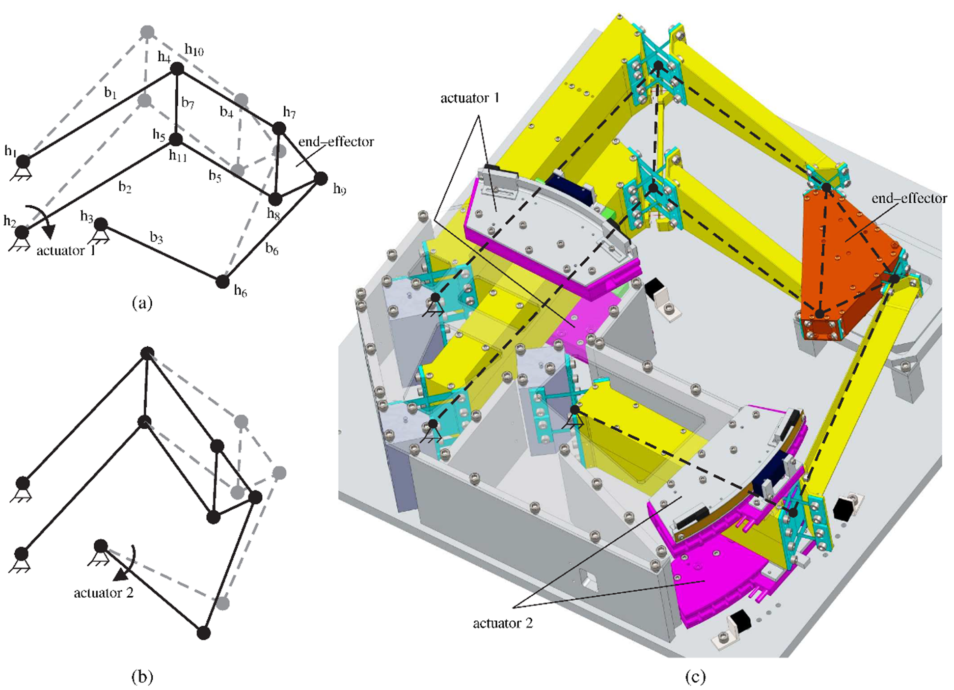 |
Figure 1. Two-DOF mechanism allowing for base mounted actuators; (a) shows the motion resulting from driving actuator 1 and constraining actuator 2; (b) shows the motion resulting from driving actuator 2 and constraining actuator 1; (c) shows a drawing of the mechanism with top plate removed |
Figure 2 shows the constraints and free motions of the two parallel beams analyzed at hinge h11. It is as if the four-bar mechanism b1–b7–b2–base is being assembled, and joint h11 is the last connection in the loop to fit together. Again, the analysis is made assuming that each hinge permits exactly 1 rotation, the bars are rigid, and actuator 1 constrains exactly one DOF. In-plane there are four constraints, xB, yB, φA, and φB. The rotational constraint between φA and φAB is however released by hinge h11. Therefore, the four-bar mechanism is constrained three times in-plane, which makes the mechanism exactly constrained in-plane. In the out-of-plane direction, however there are six constraints: zA, ψA, θA, zB, ψB, and θB, while three constraints are required for an exactly constrained four bar mechanism. The four bar mechanism is three times overconstrained.
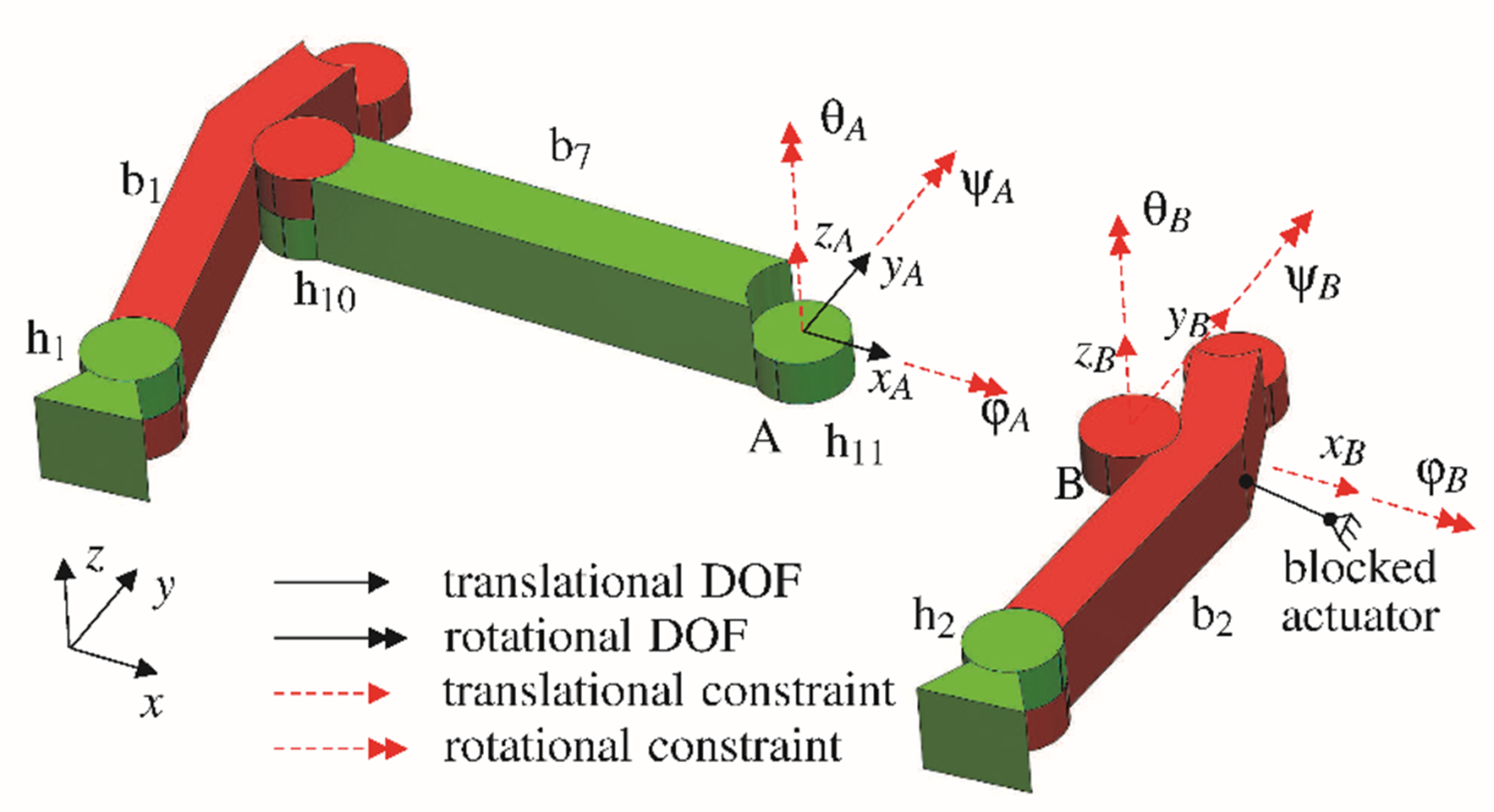 |
| Figure 2. Constraint analysis by opening loop h1–b1–h10–b7–h11–b2–h2–base. The DOFs (solid vectors) and constraints (dashed vectors) are shown for points A and B. |
The kinematics of the connection to the end-effector is shown in Figure 3. The actuators are assumed constrained, in which case the mechanism is then simplified to four rigid bars, b4, b5, b6, b8, and six hinges. Three in-plane DOFs, xC‘, xD‘ and yE‘’ are constraining the in-plane mobility of the end-effector, b8, exactly. However, the out-of-plane mobility which should be constrained three times is constrained nine times by zC,φC’, ψC‘, zD, φD’, ψD‘, zE, φE’’ and ψD‘’. Therefore, it can be concluded that subassembly 2 is overconstrained six times.
 |
| Figure 3. Analysis of the constraints on end-effector b8. The DOFs (solid vectors) and constraints (dashed vectors) are shown for points C, D, and E. Actuators 1 and 2 are considered to be constrained. For displaying purposes hinges h4 and h10, and hinges h5 and h11 are spaced apart, this does not influence the constraint analysis. |
In a two-dimensional planar analysis of the two-DOF mechanism the nine rigid bars, including the base, with each three DOFs sum up to 27 DOFs. The eleven hinges each constrain two DOFs so there are 22 constraints in total and only five DOFs remain in the system. The three rigid body modes of the mechanism are not considered, and therefore subtracted from the system’s DOFs. Then, there are two DOFs more than there are constraints as is summarized in Table 1. Because the mobility is twofold, there are no overconstraints in-plane. With the two actuators the mechanism in-plane is exactly constrained.
The mechanism can also be analyzed including the third dimension by Grübler’s criterion. The nine bars now give rise to 54 DOFs, the four hinges impose 55 constraints, and 6 rigid-body modes are not considered. As shown in Table 1 this results in nine more constraints than there are DOFs. Because the two-DOF mechanism has a mobility of two, there have to be nine overconstraints. The overconstraints do not appear in the two-dimensional analysis, but do show up in the three-dimensional analysis. Apparently, the overconstraints are related to the out-of-plane directions. There are nine releases and two actuators required to obtain an exact constraint mechanism.
| 2D | 3D | ||
| # Rigid bars (n=9) | 27 | 54 | DOFs |
| # Constraints of hinges (s=11) | -22 | -55 | DOFs |
| Rigid body modes of mechanism | -3 | -6 | DOFs |
| DOFs – constraints – rigid body modes (M) | 2 | -7 | DOFs |
| Real mobility | 2 | 2 | DOFs |
| Overconstraints | 0 | 9 |
Table 1. Constraint analysis of the 2 DOF stage using Grübler’s criterion
The locations and directions of the nine releases are shown in Figure 4. Arms b4, b5 and b6 each have a notch hinge and a torsionally complaint profile to releases 2 directions, shown in Figure 6. Each end of bar b7 has a leaf spring with a perpendicular wire-flexure running through the center, and a notch-hinge flexure. In contrast to the hinge-flexures used at the mechanism joints, a stress release-flexure does not need a large range of motion. Therefore, the bending and torsion releases are designed to make small rotations only. However, since there are 3 DOFs at each end, the design is underconstrained. This results in an internal vibration mode, being a twist of the linkage about its longitudinal axis. However, FEM analysis shows that the natural frequency of this mode is sufficiently high and should not interfere with the dynamics at the end-effector or destabilize the controller.
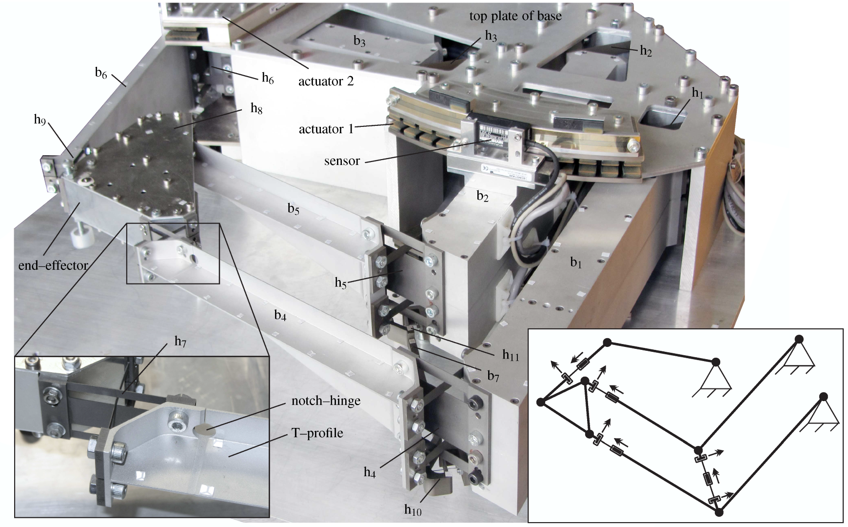 |
| Figure 4. Photo of the two-DOF mechanism with skeleton frame showing the nine release locations and orientations, double arrows indicating rotational DOFs. |
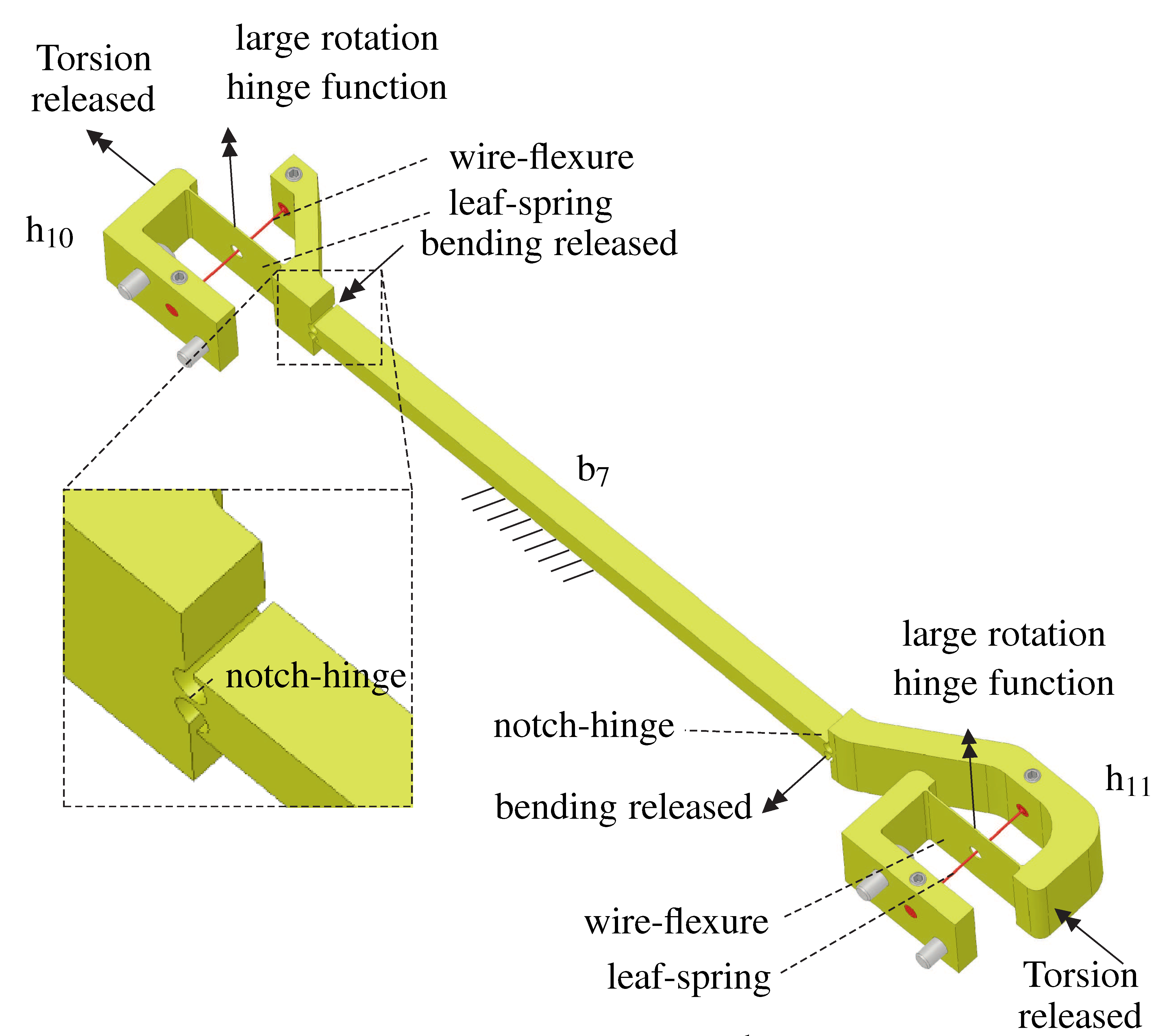 | 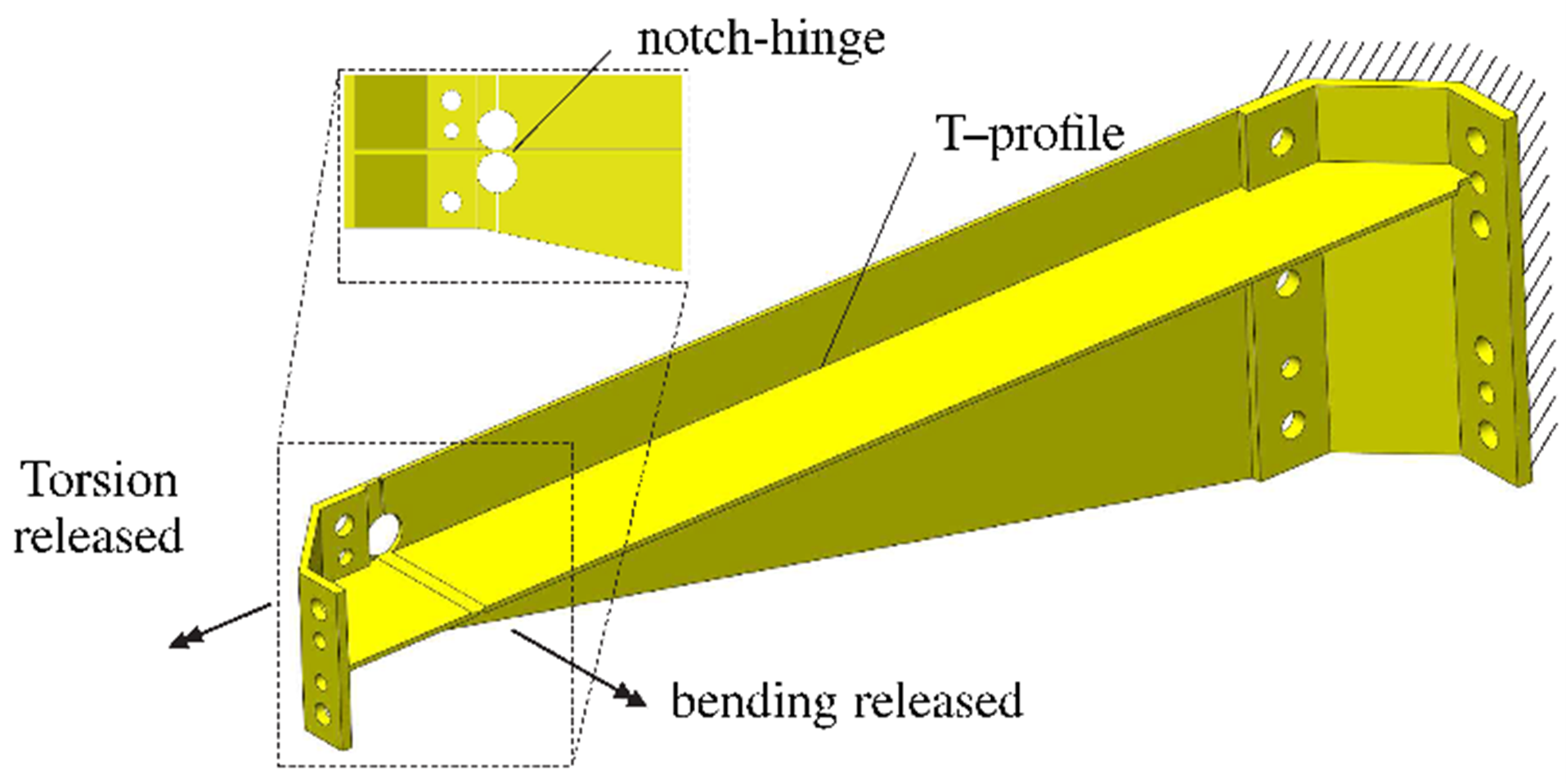 |
| Figure 5. DOFs of bar b7 | Figure 6. Torsionally and bending compliant arm introducing 2 releases per arm. |
Principle
To ensure a deterministic and therefore predictable behavior with the many specifically designed and assembled parts a (flexure-based) design can be made exactly constrained. Two methods are shown to analyze the constraints of the mechanism. The method of opening the kinematic loop and analyzing the constraints meeting from the two sides shows possible under- and overconstraints, and their direction. Grüblers criterion can serve as a check on the number of constraints and the mobility. The method using Grüblers criterion requires background knowledge on either the number of overconstraints or the mobility to calculate the mobility or the number of overconstraints, respectively. A mathematical third method using the multibody model with singular value decomposition undoubtedly determines the amount of overconstraints companied with their indeterminate stress modes, and the mobility with the accompanying motions is shown in [1].
The two degrees of freedom mechanism consists of three kinematic loops. With ideal rigid bodies and single degree of freedom hinges each kinematic loop gives rise to three overconstraints adding
to the total of nine overconstraints in the mechanism. To obtain an exact constraint mechanism we implemented nine releases in the fabricated set-up, which resulted in predictable stiffnesses and modal frequencies of the mechanism.
Developed by University of Twente
D.M. Brouwer, K. G. P. Folkersma, S.E. Boer, R.G.K.M. Aarts
Referentie Bron
[1] D.M. Brouwer, K.G.P. Folkersma, S.E. Boer, and R.G.K.M. Aarts, Exact Constraint Design of a Two-Degree of Freedom Flexure-Based Mechanism, Journal of Mechanisms and Robotics (ISSN 1942-4302) 5(4), 041011, pp. 10 (2013). DOI: 10.1115/1.4025175
[2] Wijma, S.E. Boer, R.G.K.M. Aarts, D.M. Brouwer, W.B.J. Hakvoort, Modal Measurements and Model Corrections of a Large Stroke Compliant Mechanism, Archive of Mechanical Engineering, ISSN (Online) 2300-262X, 61(2), pp.347-366, 2014. DOI: 10.2478/meceng-2014-0020.
[3] D.M. Brouwer, S.E. Boer, J.P. Meijaard, R.G.K.M. Aarts, Optimization of release locations for small self-stress large stiffness flexure mechanisms, Mechanism and Machine Theory, Volume 64, pp. 230-250 (2013). DOI: 10.1016/j.mechmachtheory.2013.01.007