Chapter 2 - Design using flexures
Collimator for CT scanner with 35g centrifugal load
Computed tomography (CT) scanners (formerly known as computed axial tomography or CAT scanners) are used in radiology to obtain non-invasively detailed internal images of the human body. Here, a rotating X-ray tube and a row of detectors are placed in a gantry to measure X-ray attenuations by different tissues. To change the shape and intensity of the X-ray beam, shutter blades and filters are used as part of a so-called collimator, which is placed directly behind the X-ray source (see Figure 1). Due to the high rotational speed up to 250 rpm, and resulting centrifugal forces of up to 35g, the heavy blades typically made out of lead or tungsten create very unfavorable loads to the guiding system of the collimator.
Description
In Figure 2, a cross section of the collimator is shown, indicating lead screw drives and linear guide ways for moving the blades. Since the mechanisms are not allowed to block any part of the X-ray beam, a large drive offset is applied. This is acceptable here, in view of the low adjustment speed during scan, not hampering positioning performance due to dynamic limitations. In view of the large centrifugal forces and the targeted repeatability for positioning the blades, a light-weight and stiff frame structure was used with favorable load introduction close to the so-called system lines. Aluminum extrusion profiles are used for cost reasons (see Figure 3 and 4), which include extruded monolithic flexure hinges to kinematically mount the blades to the linear guide ways and lead screws. The latter are pre-tensioned via plastic nuts (see Figure 4). A traditional Oldham coupling is used to radially relieve the nut from the spindle, which is significantly deforming under the high g-forces.
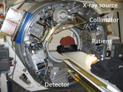 | 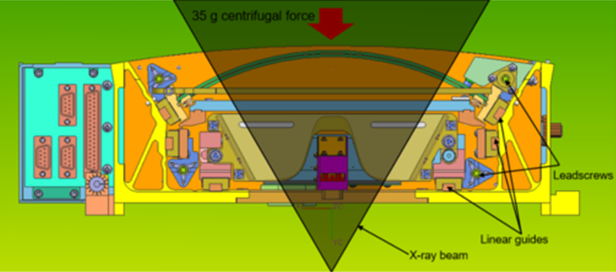 |
| Figure 1. Modern CT scanner, which rotates around the patient, typically at 250 rpm to capture X-ray images of the tissue in the human body. | Figure 2. Design of the collimator, which consists of curved shutter blades made out of tungsten and filters with linear straight guides and drive systems outside the X-ray beam. |
The open collimator frame obtains its torsional stiffness from the (closed) extruded tubes at both sides (see Figure 3), similar to a refrigerator with a (horizontal) tube behind the vegetable drawer.
Here, the shutter blades are made of tungsten, which makes a separate supporting structure superfluous. The blades have an arc-shape, to transmit centrifugal forces in the plane of the blade sheet to the guide ways with minimal deformation (see Figure 5). The curved shape makes adjustment of mutual parallelism relatively easy, viz. by twisting the blade that has an internal degree of freedom via a strut.
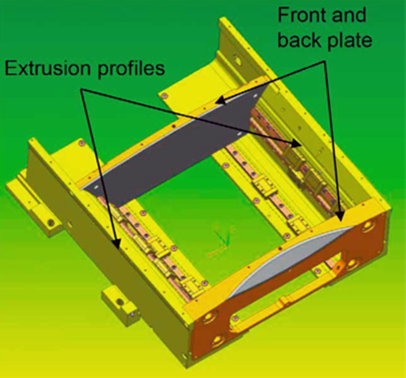 | 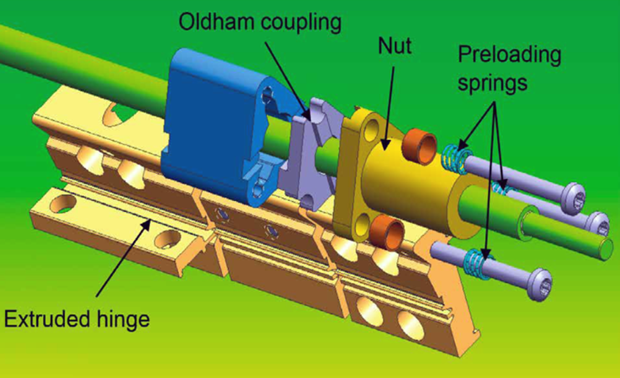 |
| Figure 3. Design of the collimator frame, which obtains torsional stiffness from the (closed) tubes, similar to a refrigerator with a (horizontal) tube behind the vegetable drawer. | Figure 4. Lead screw drive consisting of a plastic nut, which is radially relieved from the guiding system via an axially preloaded (traditional) Oldham coupling. |
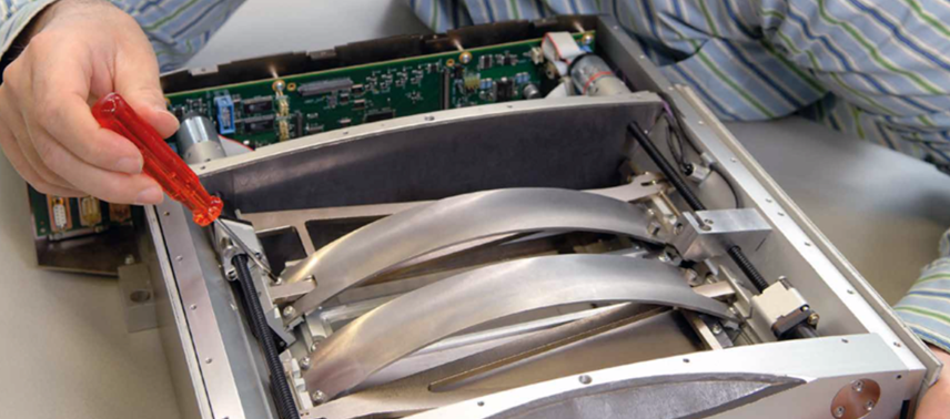 |
| Figure 5. Final assembly of the collimator with two curved shutter blades. |
| Application: Collimator to change the shape and intensity of an X-ray source in a CT scanner. | Realized: Prototype collimator system for Philips Healthcare. | Principle: Kinematic design, internal degree of freedom, design for stiffness through in-plane loading. |
References
[1] Beukeling, L. van, Eerden, H. van, Wim van der Hoek, 1924-2019, Een constructief leven – Ontwerpprincipes en praktijkvoorbeelden tussen kritiek en creatie, November, 2020.
Development
Michel Loos, Philips Engineering Solutions (20XX)