Material utilisation optimisation
Introduction
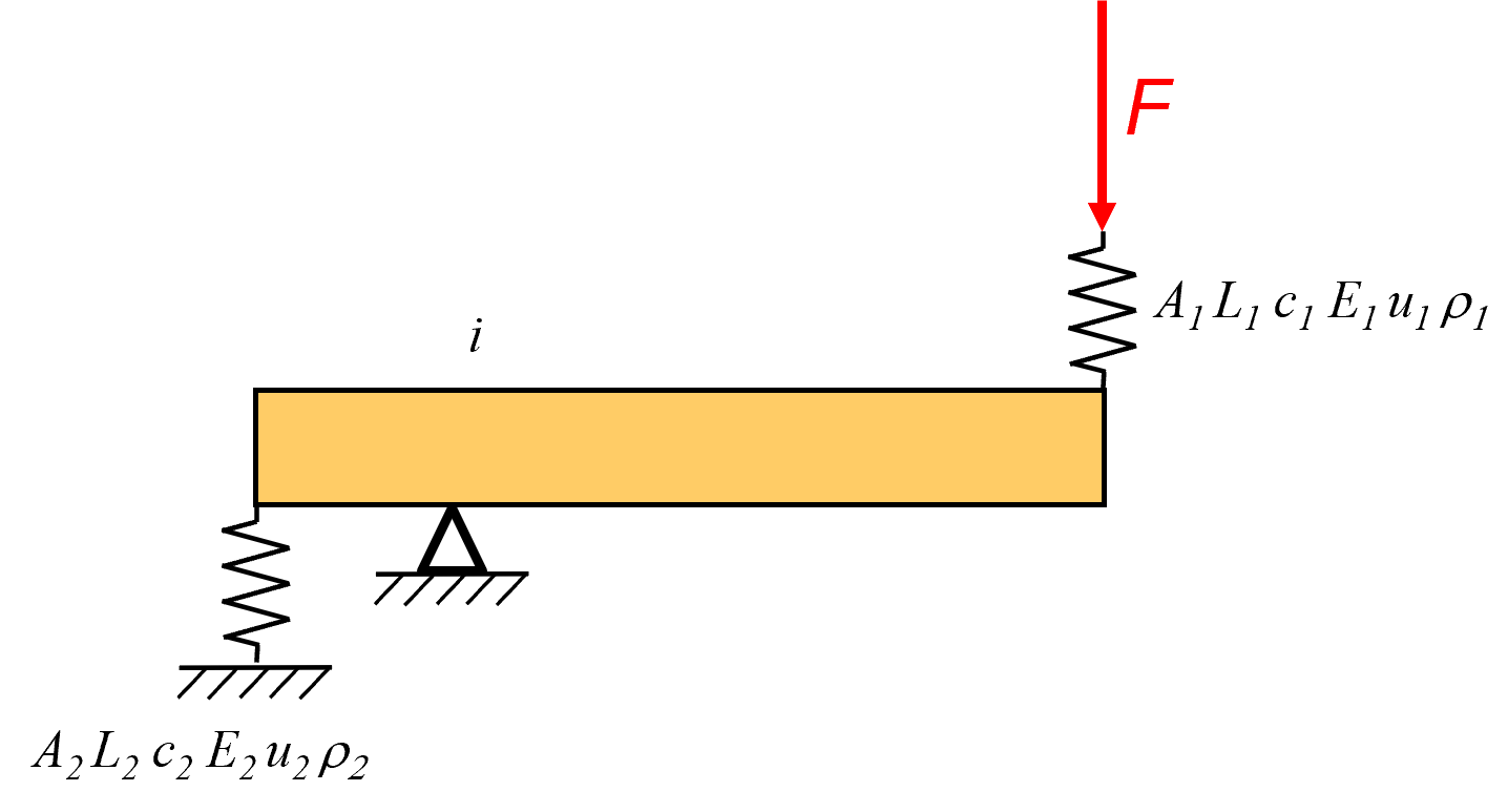
A high stiffness and a low mass can be important for a moving frame, but which parameter needs to be optimized? Typically there are multiple outputs to display in an FEM environment such a stress, strain, and displacement. The proper parameter will be derived. A strongly simplified two spring and one lever example serves as a case study for series stiffness with lever in between, and shown in Figure 1. Spring 1 and 2 have stiffness:
$$
c_1=\frac{E_1A_1}{L_1}
$$
$$
c_2=\frac{E_2A_2}{L_2}
$$
In which the Young’s modulus is $E$, the cross sectional area is $A$, and the length is $L$. The displacements of the individual springs $u$ are:
$$
u_1=\frac{F}{c_1}=\frac{FL_1}{E_1A_1}
$$
$$
u_2=\frac{Fi}{c_2}=\frac{FiL_2}{E_2A_2}
$$
In which $i$ is the transmission ratio, and $F$ the external force. The total displacement at the external force node $u$ is
$$
u=u_1+iu_2=F \left(\frac{L_1}{E_1A_1}+i^2 \frac{L_2}{E_2A_2} \right)
$$
The total mass of the springs is
$$
m_{tot}=m_1+m_2=A_1L_1\rho1+A_2L_2\rho_2
$$
$$
A_2=\frac{m_{tot}-A_1L_1\rho1}{L_2\rho_2}
$$
The compliance at the external force node $s$ is
$$
s=\frac{u}{F}= \frac{L_1}{E_1A_1}+i^2 \frac{L_2}{E_2A_2}
$$
$$
s=\frac{L_1}{E_1A_1}+i^2 \frac{L_2^2\rho_2}{E_2\left(m_{tot}-A_1L_1\rho_1\right)}
$$
The partial derivative of the compliance to the area $A_1$ is equal to 0
$$
\frac{\partial s}{\partial A_1}=-\frac{L_1}{E_1A_1^2}+i^2 \frac{\rho_1 \rho_2 L_1 L_2^2}{E_2\left(m_{tot}-A_1L_1\rho_1\right)^2}=0
$$
$$
\frac{L_1}{E_1A_1^2}=i^2 \frac{\rho_1 \rho_2 L_1 L_2^2}{E_2\left(m_{tot}-A_1L_1\rho_1\right)^2}
$$
with $i$
$$
i=\frac{\frac{E_2A_2}{L_2}u_2}{\frac{E_1A_1}{L_1}u_1}
$$
yields
$$
\frac{E_1}{\rho_1L_1^2}u_1^2= \frac{E_2}{\rho_2L_2^2}u_2^2
$$
$$
\frac{E_1}{\rho_1}\varepsilon_1^2= \frac{E_2}{\rho_2}\varepsilon_2^2
$$
$$
\frac{\sigma_1 \varepsilon_1}{\rho_1}= \frac{\sigma_2 \varepsilon_2}{\rho_2}
$$
$$
\left(\frac{\textrm{strain energy}}{\textrm{mass}}\right)_1= \left(\frac{\textrm{strain energy}}{\textrm{mass}}\right)_2
$$
Match of strain energy per unit mass
Note that the same steps can be taken to get the maximum stiffness with a certain amount of volume. The result is:
$$
\sigma_1 \varepsilon_1= \sigma_2 \varepsilon_2
$$
Match of strain energy density
Principle
To get the maximum stiffness with a certain amount of mass:
Match of strain energy per unit mass
Example
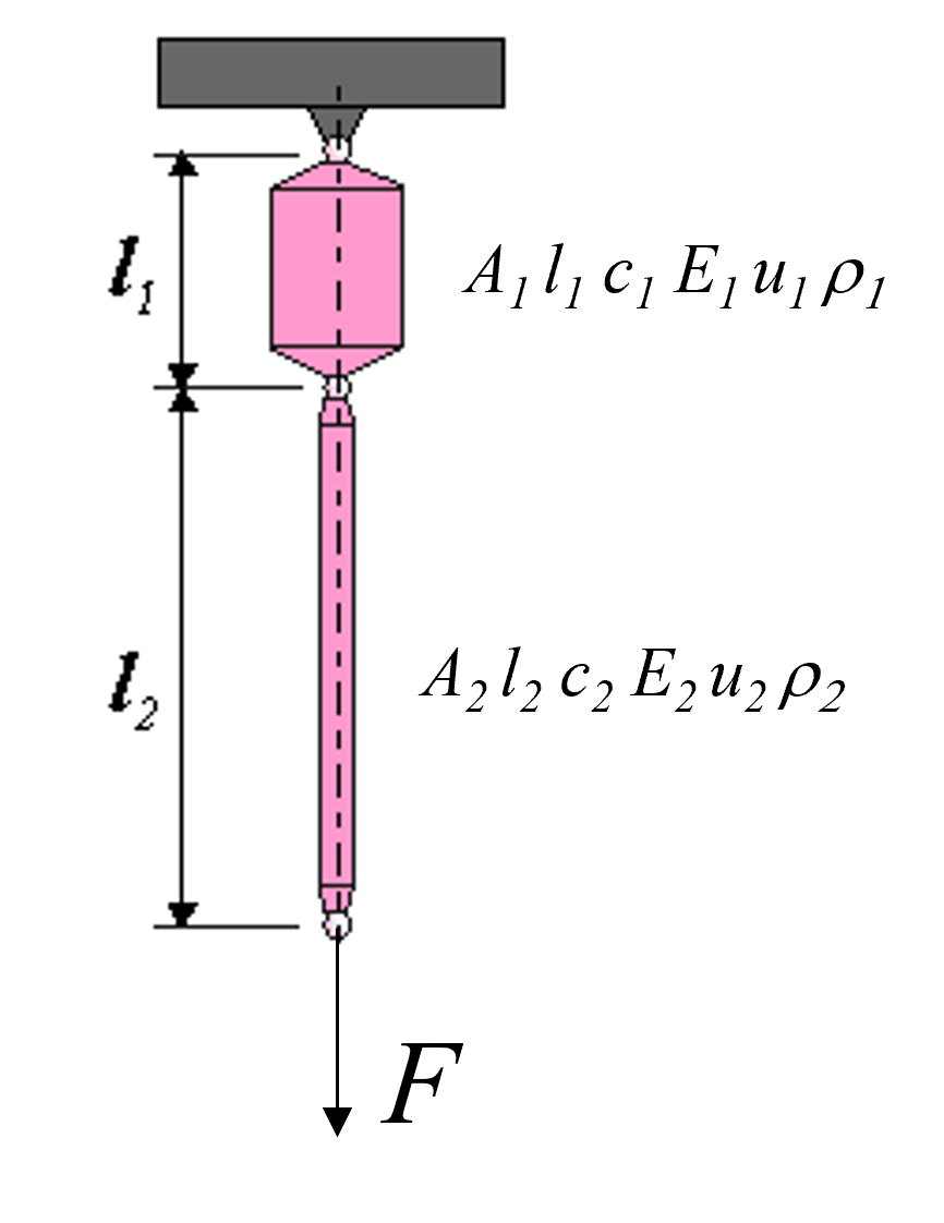
So, to maximize the series stiffness of the two springs shown in Figure 2
$$
\frac{\sigma_1 \varepsilon_1}{\rho_1}= \frac{F_1\Delta L_1}{A_1L_1\rho_1}=\frac{F_2\Delta L_2}{A_2 L_2\rho_2}=\frac{\sigma_2 \varepsilon_2}{\rho_2}
$$
with
$$
\Delta L_1= \frac{F_1 L_1}{E_1 A_1}
$$
and
$$
\Delta L_2= \frac{F_2 L_2}{E_2 A_2}
$$
$$
\frac{F_1^2}{A_1^2 E_1 \rho_1}=\frac{F_2^2}{A_2^2 E_2 \rho_2}
$$
with $F_1=F_2$
$$
A_1^2 E_1 \rho_1=A_2^2 E_2 \rho_2
$$
with $E_1=E_2$ and $\rho_1=\rho_2$ then $A_1=A_2$.
Parallel springs
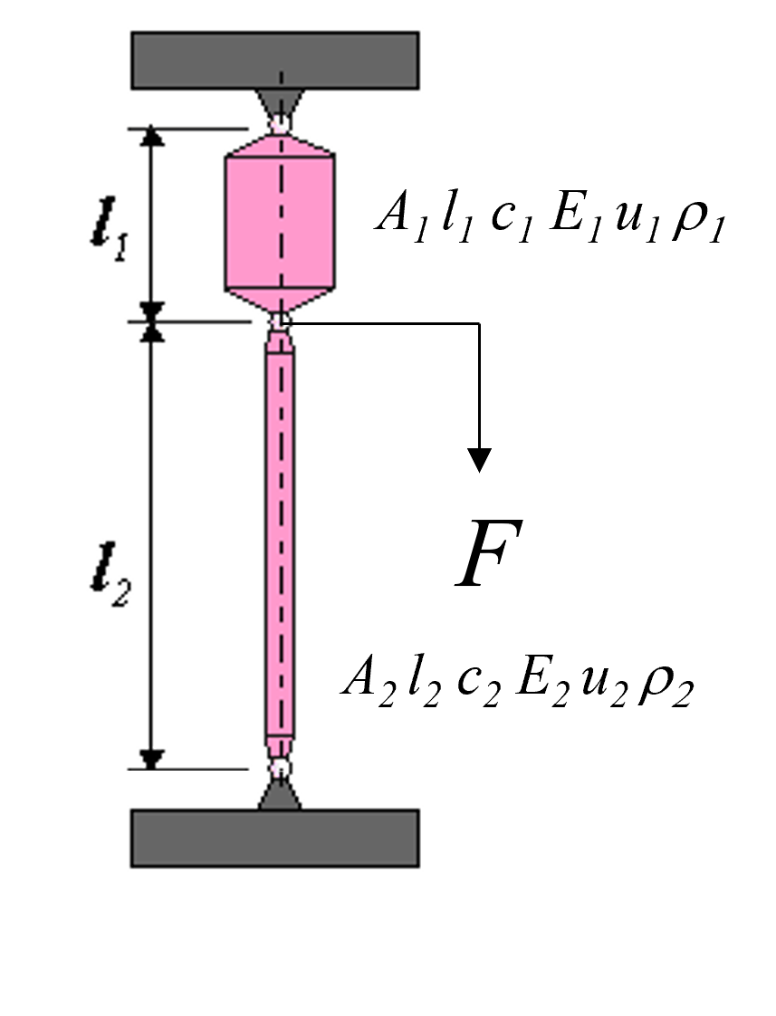
The optimum for a parallel set of springs, Shown in Figure 3, can be derived in a similar manner. However, taking the partial derivative of the stiffness or compliance to the area $A_1$ and equating to zero, leads to the minimum stiffness. The maximum stiffness is found at on of the extreme values for $A_1$ either extreme of $A_1$. If
$$
\frac{E_1}{\rho_1 L_1^2}>\frac{E_2}{\rho_2 L_2^2}
$$
Then use all material to increase $A_1$ as much as possible, otherwise use all material to increase $A_2$ as much as possible.
Developed by University of Twente
- Dannis Brouwer, Jaap Meijaard