Anisotropic eddy current damper
In systems with challenging dynamic requirements, it is often necessary to add damping to the system. In particular very clean constructions in vacuum tend to have very little damping of their own. Eddy current dampers have a number of nice properties:
- Contactless, therefore:
- no particle contamination
- no friction
- no parasitic stiffness in any direction (also no magnetic parasitic stiffness)
- no critical alignment
- Vacuum compatible
- Predictable damping
- For 2 DoF planar movements the damping in orthogonal directions can be tuned independently
An eddy current damper is very similar to a flat Lorentz motor: one part is a magnet assembly, mostly with back irons and permanent magnets, the other part is a coil (in case of a Lorentz motor) or just a solid electrical conductor (in case of an eddy current damper). The solid conductor in fact just works as a short-circuited coil.
When the conductor moves inside the magnet assembly, the magnetic flux through the conductor changes, causing an induction voltage. Since current can flow anywhere inside the conductor, the induction voltage causes eddy currents to run inside the conductor. These run perpendicular to the flux from the magnets, causing Lorentz forces in the plane of the conductor to act between magnet assembly and conductor.
From this it follows that the force is proportional to the square of the flux density, and to the electrical conductivity of the conductor:
- the induction voltage is proportional to the flux density
- the current density is proportional to the induction voltage divided by the electrical resistance of the conductor
- the Lorentz force is proportional to the product of current density and flux density
The induction voltage is also proportional to the relative speed of the conductor with respect to the magnet assembly, causing the eddy current damper to behave as a linear viscous damper. The above only valid at low speeds, because it neglects the electrical time constant of the conductor, causing a phase shift in the currents, causing a lower damping value at high speeds. However, when using an eddy current damper to damp resonances, it is almost certain that the speeds are very low, and this effect can indeed be completely neglected.
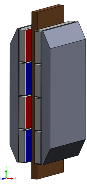
By designing the magnet circuit in a way that the change of flux in the conductor is different in two different directions, an anisotropic damping characteristic can be obtained, which can be very useful. For instance, when only damping in one direction is needed, and the damping in the perpendicular direction should be zero, this can be obtained by making the magnets wider than the conductor, so the flux though the conductor does not change when moving in the direction in this direction. In Figure 1a, the damping will be zero in the z-direction, almost zero in x-direction, and significant in y-direction. The eddy current damper has 8 magnets of 40 MGoe, each with a size of 40x20x5 mm3, and copper conductor of 4 mm thickness, 30 mm wide and 80mm overlap. The damping at low speeds is around 200 Nm/s.
In general, a rough estimate of the damping value in y direction for a design like this would be around 10 Ns/m per cm3 of conductor between the magnets for an aluminum conductor, and 20 Ns/m per cm3 for a copper conductor. For a more accurate estimate, a finite element calculation must be made.
 |  |
| (a) | (b) |
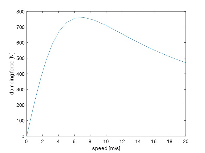
Figure 1. a) Example for an 8 magnet with copper conductor eddy current damper. b) Finite element calculation of the damping force as a function of the speed.
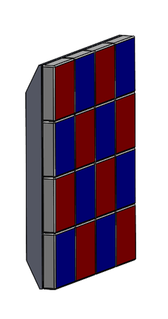
The design in Figure 2 results in equal damping in two directions. An example using the anisotropic property is shown in Figure 3. A cilindrical air bearing is damped in the longitudinal direction from one side of the shaft only without introducing a moment on the bearing. Therefore the force is directed through the center of gravity of the bearing. A sideways force will result, but the bearing can manage that.
 |  |
| (a) | (b) |
Figure 2. A checkered magnet assembly for damping in 2 directions.
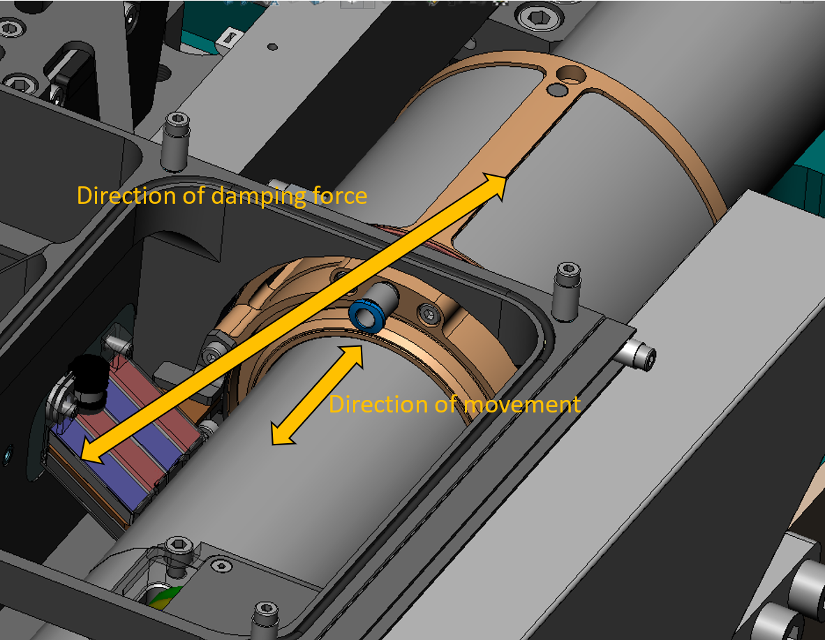
Figure 3. Damping of a cilindrical air bearing.
References
–
Development
Peter Rutgers