Symmetry in actuation – Over-actuation
It is recommended in [1] to incorporate symmetry to the maximum extent possible in properties of machine elements (e.g. mass- and force distribution or stiffness), the entire instrument and properties of the environment. In designing, manufacturing, assembling and operating a precision instrument, any departure from symmetry has to be weighed against the resulting compensation to overcome problems produced by the asymmetry. To avoid thermal asymmetry, inducing significant distortions of the machine components, a thermal center as symmetry axis for thermal expansions can be applied [2]. To overcome the effect of asymmetry about the horizontal plane, caused by gravitational forces, machines can be equipped with a vertical axis, e.g. the LODTM [3]. Three dimensional symmetry is superbly achieved by a tetrahedral structure, e.g. the Tetraform by Lindsey of NPL [4], [5], [6]. In addition to its proponents, Hocken mentions some adversaries of symmetry [7], e.g. vibrational energy is not reduced by symmetric design, and in fact it is often enhanced.
Description
In semiconductor lithography stages, 6 DoF actuation was applied for a long time, primarily to avoid unknown deformations of calibrated interferometer mirrors at the side edges of the so-called wafer chuck. Typically, 3 vertical and 3 horizontal actuators were applied in 120 deg. symmetry (see Figure 1a), integrated in pockets for weight reduction and allowing to actuate in a horizontal plane more or less through the center of mass, minimizing the drive offset. Due to a small mismatch in practice, however, typically in the order of a few 0.1 mm, a moment load arises, which has to be compensated by the vertical actuators, either in push (upward) or in pull direction (downward). Over time, acceleration was increased to improve wafer throughput, and at the same time, better positioning accuracy was required in view of tighter overlay budget in the lithography process. For that reason, higher control bandwidth was needed, which in turn, enforced higher eigenfrequencies of vibration modes. Closed boxes were applied, and materials applied with somewhat higher Young’s modulus, which resulted in increase of the first resonant frequency above 1 kHz. These improvements, however, were not sufficient, and bandwidth increase was essentially limited by the (first) torsion mode that was effectively excited by the vertical actuators mentioned above, pushing and pulling on the chuck to counteract the moment load due to the drive offset mentioned above.
To mitigate this fundamental limitation, over-actuation was considered and first tested in an Over-actuated test rig at ASML (see Figure 2). An aluminum chuck was provided with 3 vertical actuators for traditional control (see Figure 3a), and next, 4 vertical actuators were used. As long as force actuators are used, such as Lorentz actuators with (very) limited stiffness (position dependency) in the order of 1e3 N/m, hardly any over-determination is introduced. Here, over-actuation is essentially different from statically over-determination, the latter introducing internal stress and uncertainty in shape. For both the traditional and over-actuated case, the transfer functions from force to position and from moment to orientation angle. By the application of X-Y symmetric via over-actuation, the excitation of the torsion mode, here at 130 Hz, was avoided, and as a result, it disappears from the transfer function, allowing for a bandwidth increase from 65 to 205 Hz, even beyond the first natural frequency.
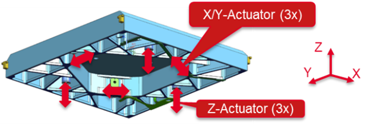  | 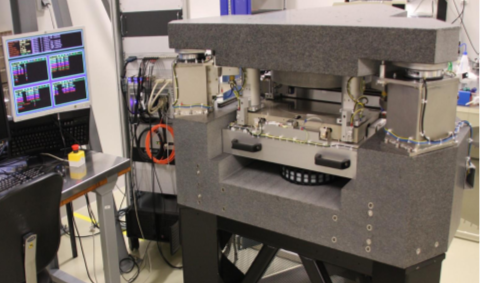 |
| Figure 1. Kinematic ‘rigid-body’ actuated wafer chuck (300 mm) (top), and symmetric over-actuated wafer chuck (450 mm). | Figure 2. Over-actuated test rig at ASML Research. |
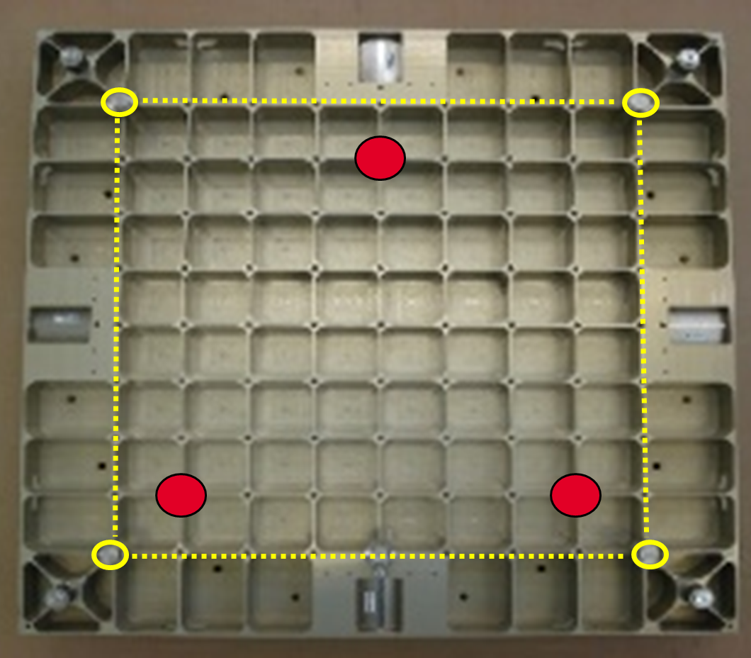 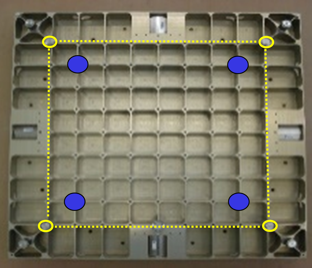 | 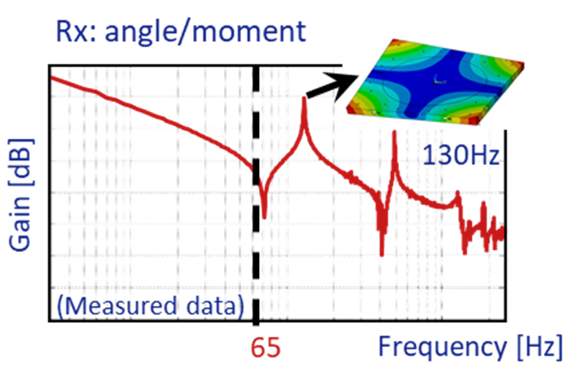 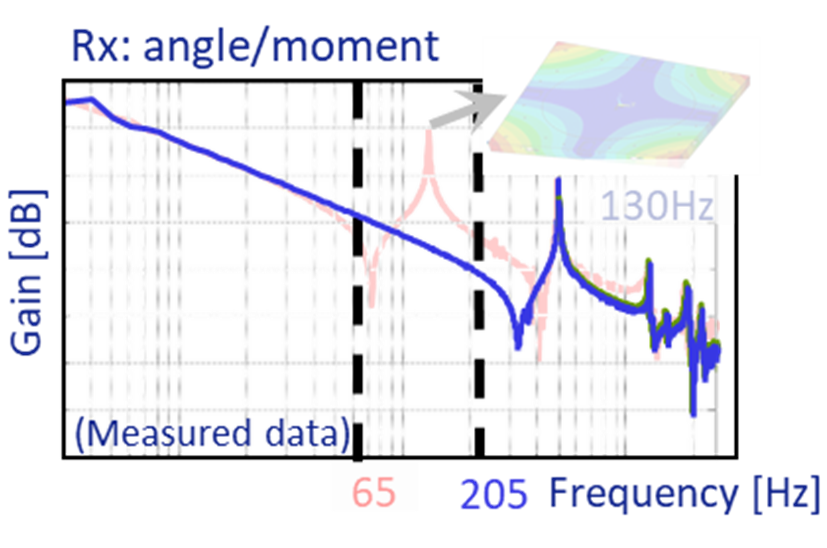 |
| Figure 3. Traditional control with 3 Z-actuators (red) (top), and Over-actuation with 4 Z-actuators (blue) (bottom). | Figure 4. Transfer function from moment to orientation angle (Rx) for traditional control (left) and over-actuation (right). Over-actuation avoids excitation of the torsion mode at 130 Hz (aluminum chuck), as a result of which it disappears from the transfer function, allowing for a bandwidth increase from 65 to 205 Hz. |
| Application: Semiconductor wafer stage. | Realized: Test rig under closed loop control to verify performance gain in terms of control bandwidth. | Principle: Application of symmetry in geometry and external loads to avoid excitation of resonant mode shapes. |
References
[1] Teague, E.C. Basic concepts for precision instrument design: Designing instruments and machines to have a high degree of repeatability, NIST, Tutorial notes, ASPE Annual meeting, Norfolk, VA, 1997.
[2] Vermeulen, M.M.P.A., Rosielle, P.C.J.N., Schellekens, P.H.J., Design of a high-precision 3D-coordinate measuring machine, Annals of the CIRP, Vol. 47/1, 1998.
[3] Donaldson, R.R., Patterson, S.R., Design and construction of a large vertical axis diamond turning machine (LODTM), Proc. of the SPIE Tech. Symposium, pp. 433-438, UCRL. 89738, 1983.
[4] Lindsey, K., Smith, S.T., Robbie, C.J., Sub-nanometre surface texture and profile measurement with Nanosurf 2, Annals of the CIRP, Vol. 37/1, pp. 519-522, 1988.
[5] Slocum, A., Precision machine design, Englewood Cliffs, NJ, Prentice Hall, 1992.
[6] Corbet, J., McKeown, Course notes in precision engineering, School of industrial and manufacturing science, Cranfield University, United Kingdom, 1997.
[7] Hocken, R., Course notes, Principles active in the design of precision machines, 1995.
[8] Munnig Schmidt, R., Schitter, G., Rankers, A., Eijk, J. van, The design of high performance mechatronics, High-tech functionality, 2nd revised edition, Delft University Press, pp. 850-853, 2014.
[9] Vermeulen, J.P.M.B., Design of high performance mechatronic systems – Lithography example, Lecture notes, 4CC10 Mechatronics Design, Eindhoven University of Technology, 2021.
Development
Wouter Aangenent, Stan van der Meulen, Marc van de Wal, ASML Research (2014)