Chapter 2 - Design using flexures
Additive manufactured laser alignment mechanism
Problem description
A mechanism is designed to manually align a laser in two rotational and two translational directions. The laser beam is manipulated by two mirrors. Available beam adjustment mechanisms can be assembled to generate the desired function. In this case however a dedicated additive manufactured flexure-based mechanism was designed to investigate the possibilities and limitations of additive manufacturing. Potentially, a monolithic design leads to low hysteresis, and the mass and stiffness can be optimized to lead to higher vibration mode frequencies.
Principle
By adjusting the angle of a single mirror the angle of the laser beam is changed. By adjusting the angle of the two mirrors as a pair, the position of the laser beam is changed. Figure 1 shows the angle adjustments are placed on top of the displacement adjustments. The use of elastic hinges and flexures makes the construction almost free of hysteresis. By using additive manufacturing as a production method the module will be monolithic contributing to a low hysteresis design. Fine pitch thumb screws are used as actuators. Tension springs preload the system allowing movement in two directions and preventing play. Because of the manual operation the adjustment procedure should be converging, meaning that the previous adjustments should not influence the latter. The adjustment order is angles first, horizontal position second, vertical position finally. Figure 2 shows the realized mechanism.
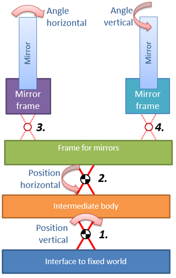
Figure 1. Schematic illustration of the adjustment stacking. Four adjustments are realised by four rotation hinges, number 1 to 4. Hinges 1 and 2 rotate both mirrors as a pair resulting in beam translation.
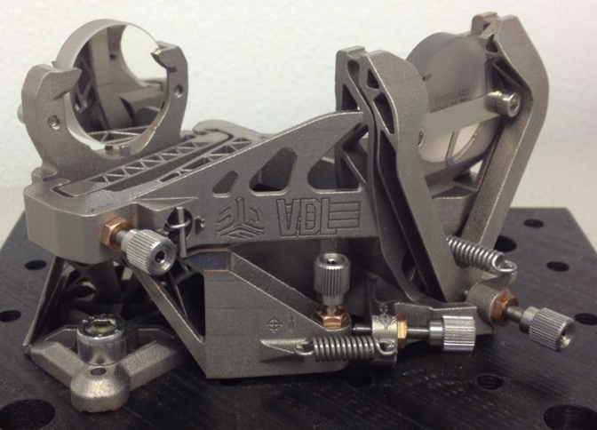
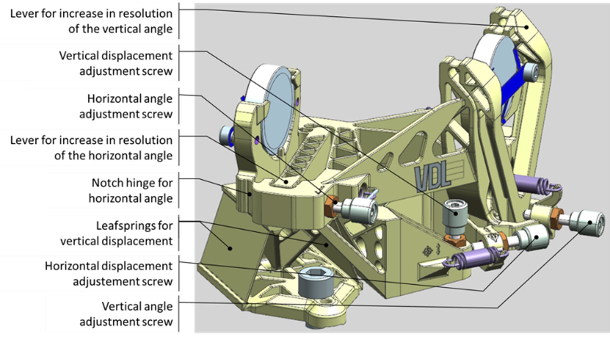
Figure 2. Realised laser alignment module.
The rotation axis for angle adjustment of the mirrors is not in the centre, which will lead to parasitic displacements of the beam when adjusting. The increase in adjustment resolution outweighs the drawback of this displacement. This choice also demands the angles to be adjusted before the translations. Figure 3 and 4 show the mechanisms for angle adjustment. The adjustment resolutions are increased using levers resulting in adjustment ratios over 10:1.
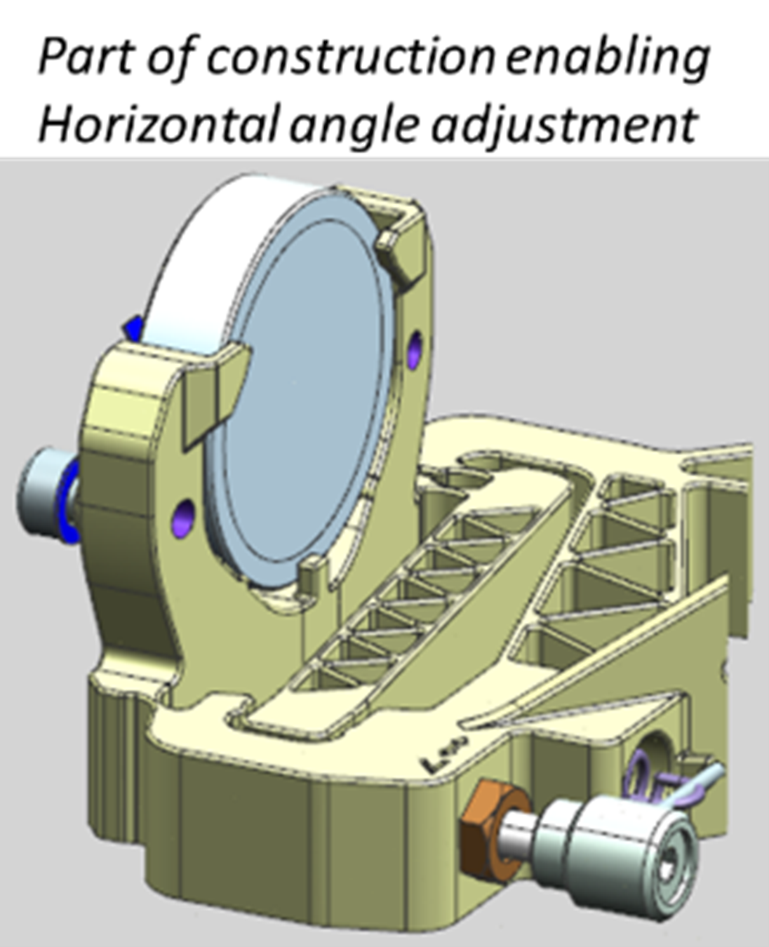
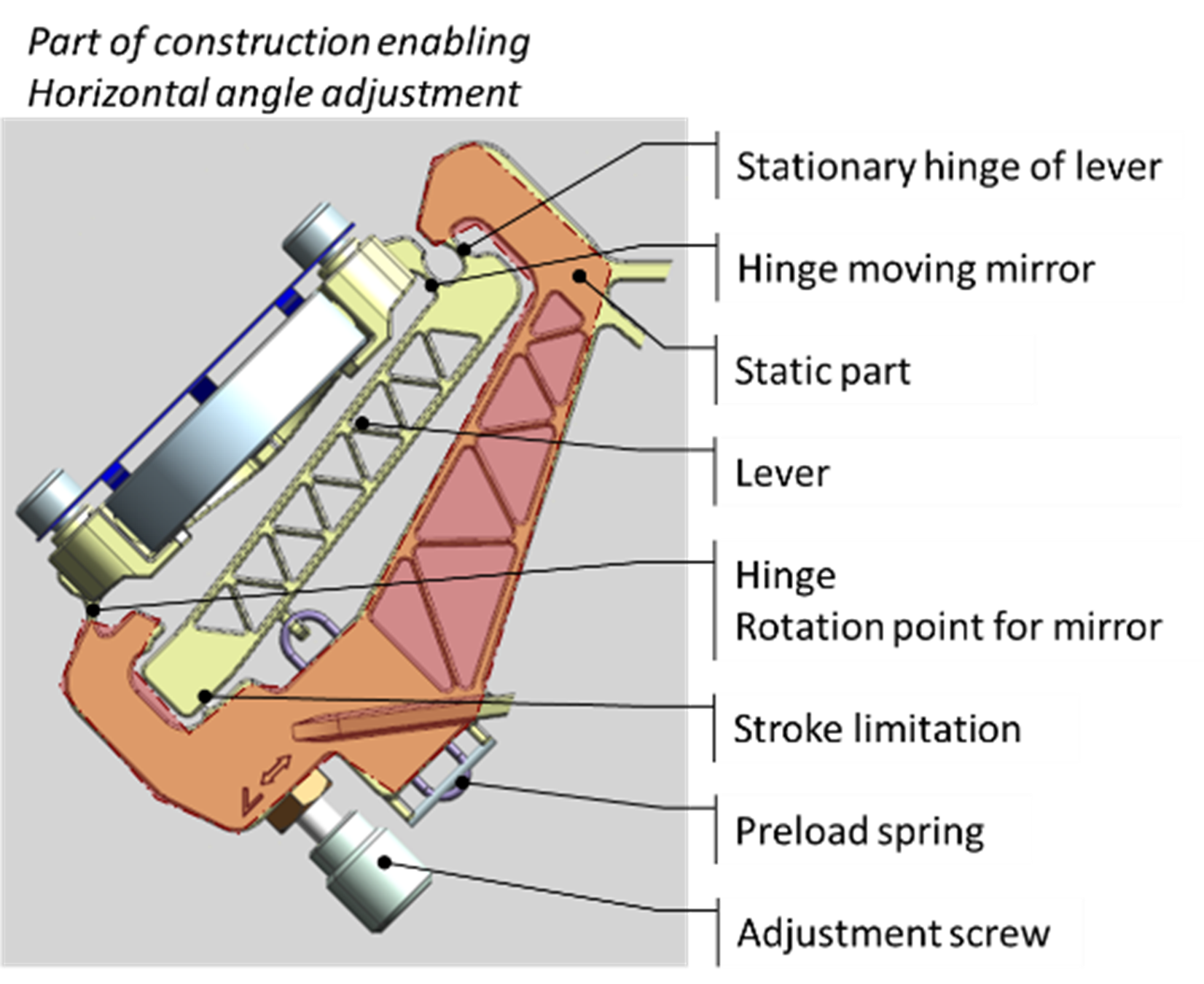
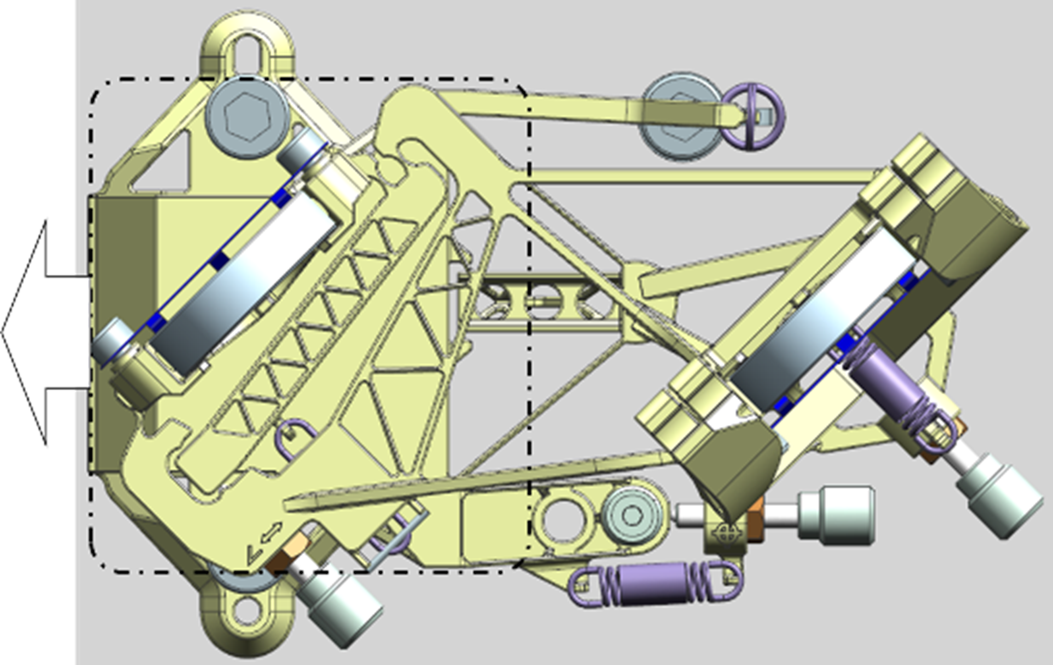
Figure 3. Horizontal angle adjustment.
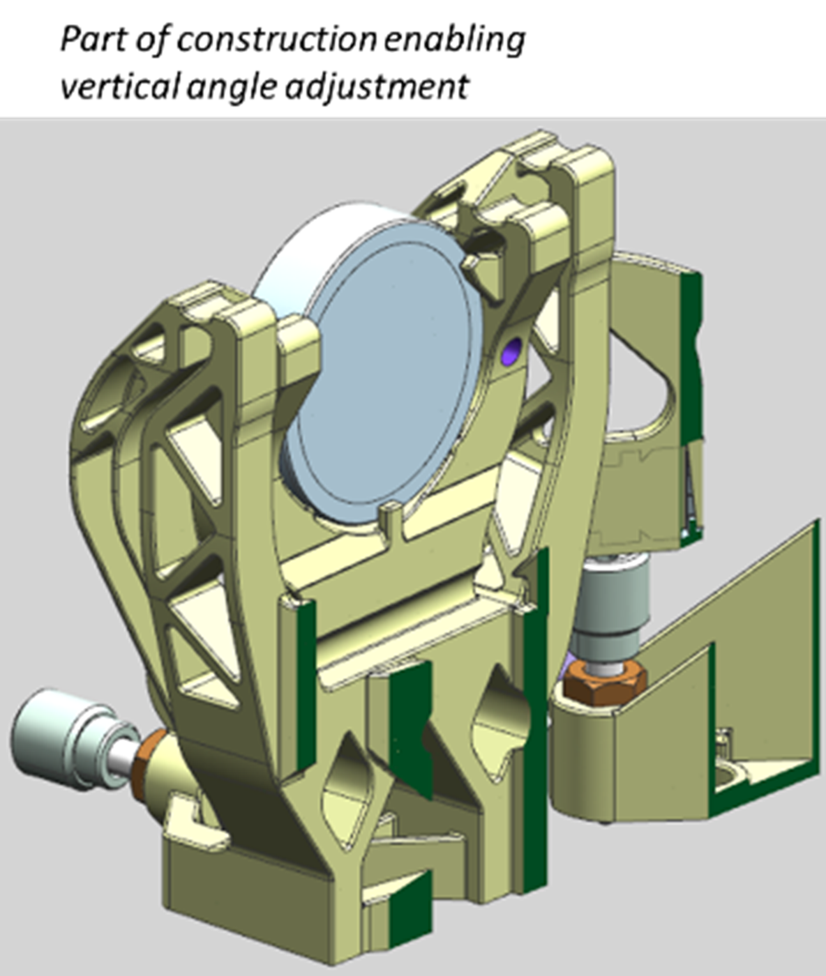
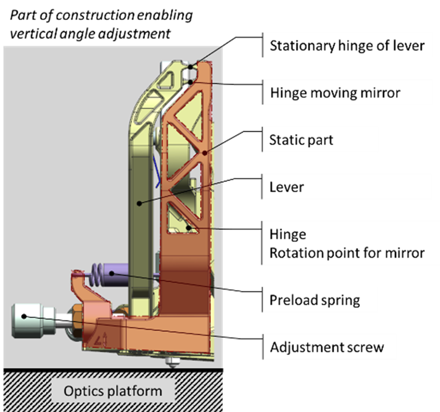
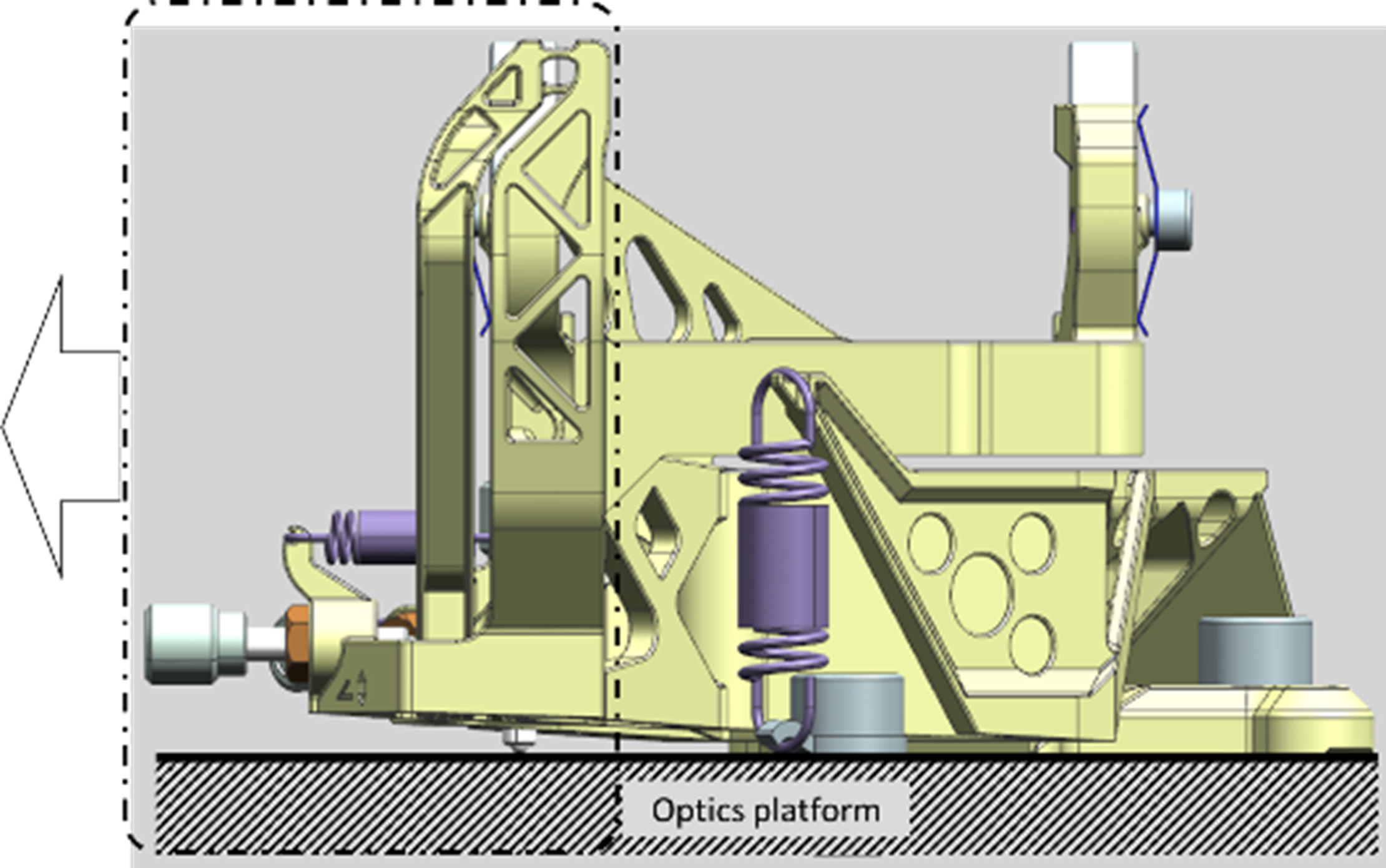
Figure 4. Vertical angle adjustment.
The horizontal displacement hinges around a remote centre of rotation, which is created by two leafsprings of which their planes remotely intersect. The axis is located between the two mirrors, see Figure 5. The sensitivity for the position adjustment is small enough to do without a transmission ratio.
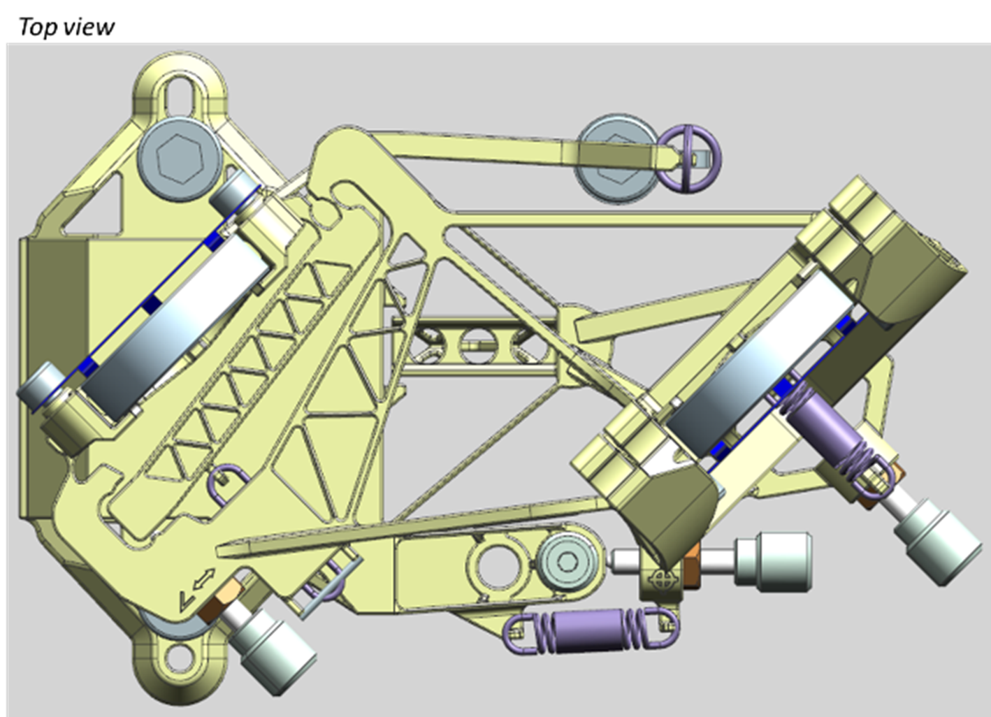
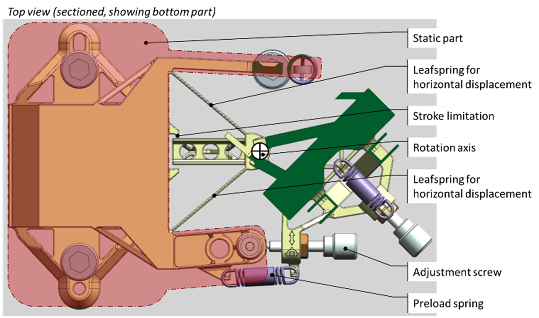
Figure 5. Horizontal displacement adjustment.
The vertical displacement is adjusted by an adjustment screw that pushes on the optics platform, see Figure 6. A remote centre of rotation is created by two leafsprings of which their planes remotely intersect at the exit mirror to not influence previous adjustments. The sensitivity for the position adjustment is small enough to do without a transmission ratio.
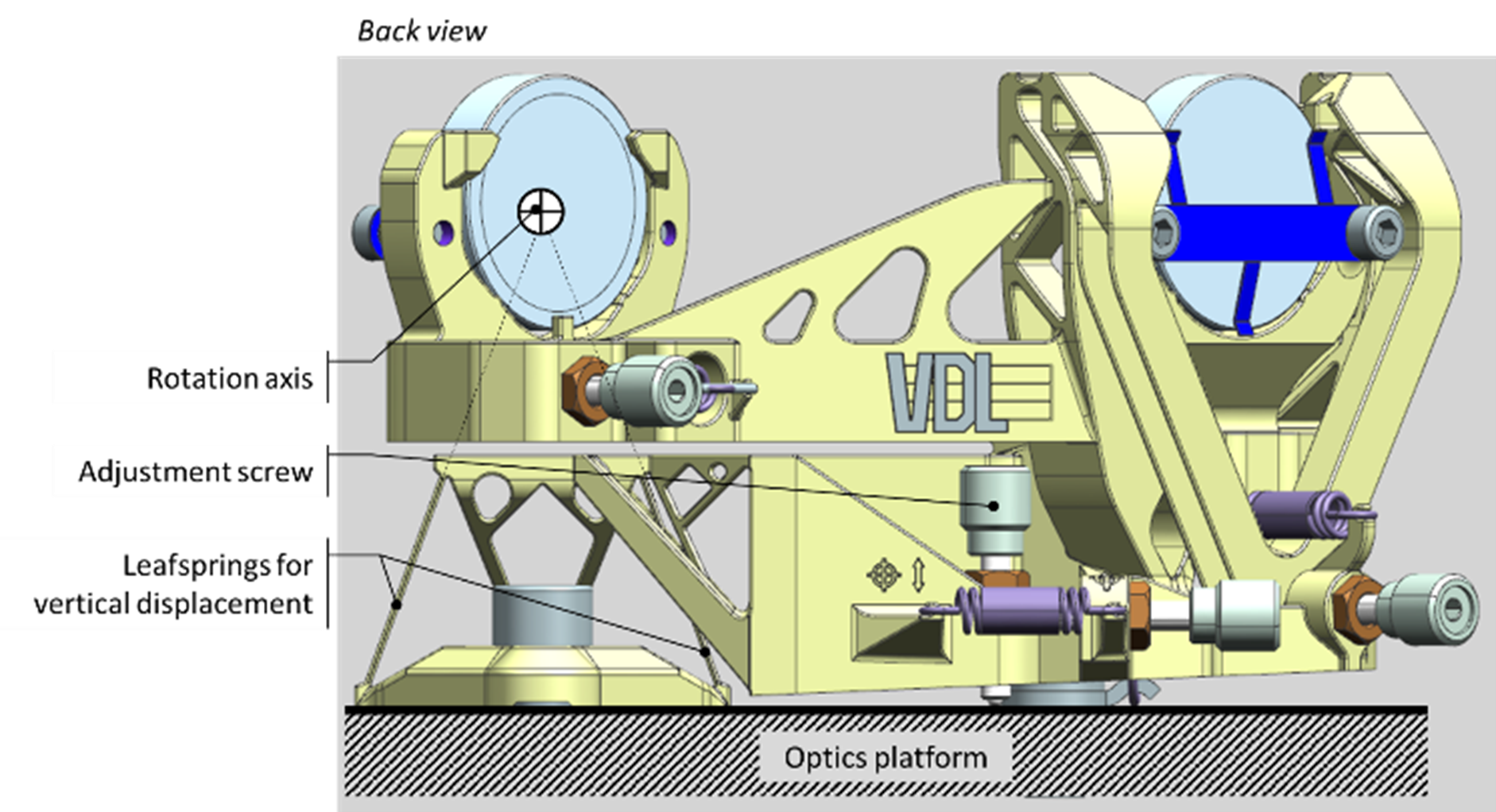
Figure 6. Vertical displacement adjustment.
The thickness and the surface texture are not very accurate when using additive manufacturing, when comparing to sheets of spring metal. Because of this the design ensures maximum stress levels, that are well below the level of plastic deformation. All movements have an integrated hard stop to prevent overloading the mechanism. The mechanism is partly self-supporting during the additive manufacturing, see Figure 7a. When separating the print from the base plate a secondary cut is made to disconnect the upper and lower half of the mechanism, see Figure 7b.
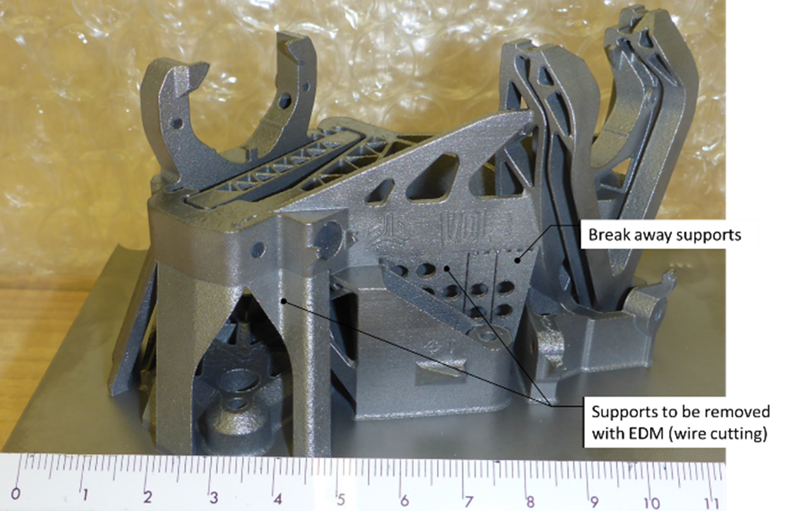
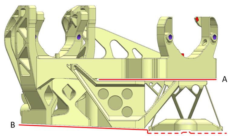
Figure 7. a) Part as printed with supports, b) wire cutting (Electric Discharge Machining) lines. Line A, separates horizontal angle and position adjustment from the supporting structure. Cutting line B creates the range for movement and separates the part from the base plate.
Conclusion
Additive manufacturing has proven to be a suitable production method for creating a flexure-based precision mechanism for this case. The design resulted in a crosstalk between adjustments that is smaller than 1:500. The repeatability of the adjustment of the laser was below 1µm.
Developed by
- Cas Wijnstok & Harry Stockx (VDL ETG T&D)