Chapter 4 - Design for dynamic stiffness
Chapter 5 - Design for damping
Anisotropic (2DOF) Tuned Mass Damper (TMD)
For a test setup it was required to move a mass of 50 kg in high vacuum. The design of the machine dictates that the drive mechanism is located in a low vacuum compartment to prevent particle contamination. The low and high vacuum compartments are split using a narrow slit as depicted in Figure 1. This requirement dictates a dynamically non-ideal design where the to-be-moved mass is connected to the motion stage via a slender connection frame. It was required to move mass $m_1$ in a point-to-point motion over a distance of 0.3m with a frequency of 7 Hz. The mass moves at a constant velocity of ~ 5 m/s over a large portion of the stroke. This motion profile requires careful design to prevent unwanted dynamics. For this particular case, parasitic eigenfrequencies larger than approximately 300 Hz are sufficient. In order to achieve these demanding requirements, the connection frame was designed to be as light and stiff as possible.
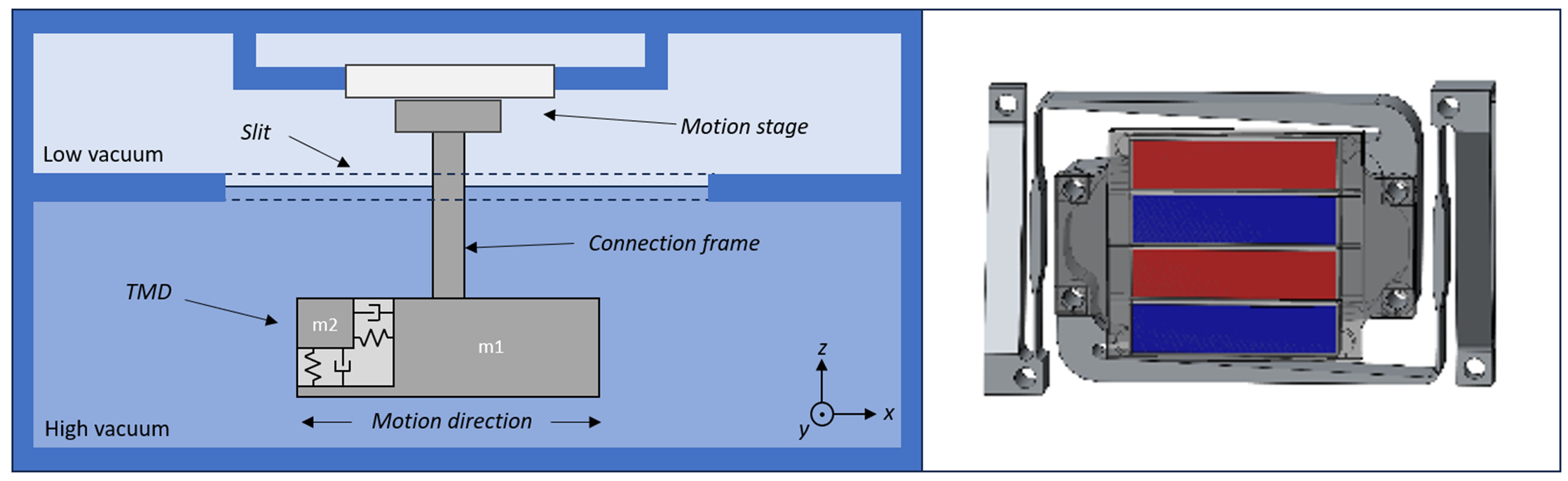
Figure 1 – On the left the (Simplified) dynamic model of the motion platform where m1 is the mass to be moved in x direction and m2 is the Tuned Mass Damper (TMD). On the right a CAD drawing of the realized 2-DOF TMD is shown.
Because of the non-ideal design space, 300Hz could not be obtained because the connection frame could not be made stiff enough resulting in a parasitic swaying motion of mass $m_1$ in x and z direction. The frequencies are 39 Hz in x-direction and 112 Hz in z-direction. To damp these modes, Tuned Mass Dampers (TMDs) are employed. As the motions were decoupled, an obvious solution would be to have two TMDs. However, the added mass of a TMD also negatively influences the dynamics of the system. To limit this, a single mass mounted on an elastic element with different stiffness in x and y direction was used to have a two-in-one solution. The design is shown on the left side of Figure 1. The elastic element is a monolithic Stavax part with reinforced leafsprings for the x-motion and tapered beams for the z-motion.
To realize damping, an anisotropic eddy current damper was utilized. A solid electrical conductor is placed between a magnet assembly. The permanent magnets are arranged in a specific pattern to obtain that the change of flux in the conductor is different in two different directions. This way, a relative damping of ~ 5% could be achieved in both directions. More information about this type of damper can be found here: Anisotropic eddy current damper – DSPE
Principle
- To reduce the mass influence of TMDs with two perpendicular damping mode shapes on the higher order dynamics, the mass can be a single common mass. The stiffness and damping can be tuned differently in the 2 directions.
Developed by
P. Rutgers (DEMCON)