Chapter 2 - Design using flexures
Chapter 3 - Design for static stiffness
Double Watts flexure mechanism for a precision vacuum adhesion and friction tester
Introduction
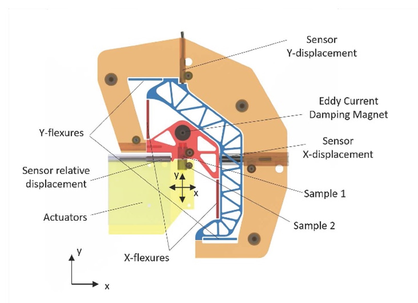
A precision vacuum adhesion and friction tester has been designed by de Vries [1] for measuring contact phenomena, such as contact stiffness, pre-sliding displacements, frictional forces, and adhesive forces. Controlling friction and adhesion at contacting interfaces is often of utmost importance for the performance of high-tech systems. Typically two force measurement systems, comprising a displacement sensor and a well-known compliance, measure the normal contact force and the friction force. A third displacement sensor measures the sample displacement. The maximum friction force to be measured is 100 mN, combined with the usable bidirectional 20 μm measurement range of the capacitive sensor the stiffness of mechanism is specified to be 5 mN/μm. A theoretical maximum friction force resolution of 0,1875 mN at 2.6 Hz and 5 mN at 1 kHz results. For the normal force measurement equivalent values were specified hence the same compliance and sensor system was used.
Concept
A two translational DOF mechanism needs to be designed. A parallel kinematic 2 DOF mechanism was considered, but a series setup might render even simpler, with better support stiffness. An interesting concept consists of two independent flexure mechanisms, one mounted on a vertical-stage for the normal force, containing sample 1, and the other mounted on a tangential stage for the friction force containing sample 2. The errors caused by parasitic forces will be minimal, as both mechanisms will measure the forces independently. Also the natural frequency in one measurement direction will not be influenced by the mass of the other measurement direction. The main issue with this concept is that the relative sample displacement sensor needs to be fixed to one of the stages, which is undesirable with a cable influencing the calibration of the compliance of the moving stage. Next, a set of a series of 2 linear flexure mechanisms is investigated. This results in an outer- and inner mechanism. For this application a very precise straight guidance is necessary and therefore some existing designs show compound parallel reinforced leafspring mechanisms, see sections 7.4, but this might be needlessly complex, compromising stiffness, compromising dynamics in particular when synchronising is omitted, poor accessibility with 2 such mechanisms, and large. One needs to keep in mind that a range of motion of 20 μm bidirectional is small, and kinematic errors typically grow proportional to the deflection to the second power. Therefore, several relatively simple four-bar mechanisms, a Parallel, Roberts, Watt and Evans mechanism, were analyzed with respect to the amount of tilt of the measurement interface and errors in the relative sample displacement when deflected 20 μm. The Watts mechanism combines the smallest translational error with a very small tilt error of 0.04 μrad. Also the contact between the two specimen are usually a sphere on a flat, making it a point contact less influenced by tilt. In fact, the values of all mechanisms are sufficiently small to be considered as an alternative to the compound parallel leafspring flexure. The in-plane parasitic rotations due to internal forces will cause larger tilt errors. A series mechanism can be directly fixed to the world, shown in Figure 1. This would significantly reduce the induced vibrations. The mass of the frame around the flexure mechanism does not need to be minimized and can be designed very stiffly. Also both displacement sensors used to measure the forces maintain a static position, resulting in high stability and it prevents the movement of sensor cables, making it less sensitive to the mechanical and electronic noise. This configuration can be manufactured as one monolithic part, resulting in almost perfect in-plane alignment of the measurement directions. A disadvantage of the series mechanism is that the outer mechanism also carries the mass of the inner mechanism, which will reduce its natural frequency in this direction and increases susceptibility to low frequency environmental vibrations. However, this susceptibility can be attenuated by reducing the mass of both the inner- and outer body. A general disadvantage of 2 DOF serial mechanisms, is the super-positioning of the parasitic translations and rotations. However, doubling the extremely small errors still renders extremely small error. The four-bar mechanisms are not statically determinate, but have one overconstraint each. This overconstraint does not lead to change of calibrated compliance due to thermal expansion. The overconstraint does increase the mechanisms support stiffness considerably.
Principle
A relatively simple double Watts flexure design is presented that combines precise straight guiding, high support stiffness, all in-plane predictable deformations, minimal influence of thermal changes on the calibration of the compliance, sensor placement obeys the Abbe principle, low hysteresis (monolithic part), and the specimen is accessible.
 |  |
| (a) | (b) |
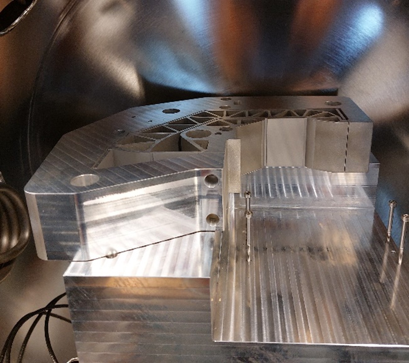
Figure 1: A double Watts motion mechanism for adhesion and friction testing. a) the concept, b) the aluminum monolithic 2-DOF motion mechanism in the vacuum chamber.
Developed by University of Twente
- Bas de Vries, Jaap Brand, Robert Jan Meijer, Matthijn de Rooij, Dannis Brouwer
Reference
- BJW de Vries, Analysis & design of a precision mechanism for micro adhesion & friction experiments in a vacuum environment, Master’s thesis, University of Twente, 2021.